thanks a lot for all the effort you put into this project.
I want to setup a small balcony nano grid with focus on learning and maybe later shift the focus towards real energy production.
Yesterday I ordered the MPPT-1210-HUS to get started. Additionally I’m thinking about a 12V 44Ah car battery and a 50W solar panel. I know that 100W is recommended; what effect will this have on the MPPT?
Two things I still don’t understand about the MPPT:
It has no CAN interface, how does it talk to the grid?
The USB data connector is type A, do I need a USB A-A cable then? If so, wouldn’t be a USB mini more convenient?
What kind of power conector do you recommend? Is there any type of standard connector for nano grids?
After the MPPT-Solar-Battery setup, what would be the next useful component? How does the grid management with multiple components work?
Everyone sends out his information and everyone adjusts to it, or is there something like an EMS involved.
There are two different kinds of MPPT charge controllers:
The MPPT 1210 HUS has rather low power and is meant for small stand-alone systems. Hence, it has the USB charging port (not meant for communication) and a serial interface, which can be used to read out its data. It is ideal for learning purposes.
The MPPT 2420 HC has higher voltage and current and follows a more modular approach. For integration with other charge controllers and a BMS (one may call it nanogrid) it has the CAN bus.
For programming of both you need an external programmer, see also here.
Unfortunately, due to chip shortages, we don’t have any of the charge controllers or BMSs with CAN support in stock at the moment. Not only STM32 microcontrollers are impossible to get, but also CAN transceivers and SMPS ICs.
In terms of nanogrid control there are two options:
Communicate set points via CAN, so the BMS would tell all the charge controllers which charging voltage etc. it requires. The idea is that you don’t need a central energy management unit. We’ve tested this in lab conditions, but there is still some more work to do.
You don’t use the CAN communication at all, but use the grid voltage to communicate the system status (called droop control, see here). This requires a more sophisticated microcontroller (e.g. STM32G474) to implement the fast DC/DC control in software. We’ve implemented it in a research project and built a small grid with it, but also due to chip shortage the ongoing development needed to be paused.
Regarding connectors: There are no standardized connectors for DC grids, unfortunately. I like the XT-90 series of connectors, where you can at least be sure that the polarity is correct. There is even a version with 2 communication pins, so you could have CAN and power in the same connector.
Ah, forgot to answer one question. If you use a smaller solar panel than recommended, there is no issue with that. The MPPT will be able to handle it, as long as the solar panel power is significantly higher than the controller idle consumption (around 0,1W)
OK, I think starting with the MPPT-1210-HUS was the right way then.
Thanks. I installed Zephyr, could compile the code and upload it to an STM Nucleo board. On a serial monitor I could watch the System working. Now I’m waiting for my board to arrive
OK, got it. I was thinking of an EMS and CAN more for strategies, e.g. a sunny day is comming, start the washing machine so later we have empty batteries to be charged.
Could you provide a link a the right search term?
OK, I’ll report, once I have something working / not working
All of these connectors are not really cheap but do a great job in a nano grid I would say. They have 4 Data pins, so CAN could be included with: VCC, GND, CAN_H, CAN_L.
Ah, didn’t know that one with 4 contacts, looks interesting. 2 would be enough for CAN, though, unless you want to have an isolated CAN with supply voltage of the optocouplers coming from the bus side.
I think I will go with the standard XT90, since there are many cheap variants for PCB mount, cable mount, …
TME seems to be a good supplier in Europe; They also sell the XT90 + 2 Pins variant:
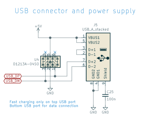
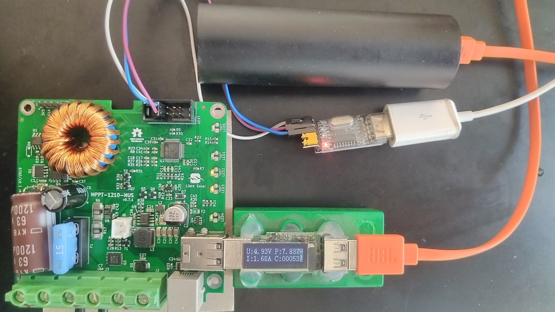
My MPPT board arrived today and now I’m eager to test it. I know, that I need to supply the board via the battery input with around 12V. Programming is also clear to me. What I still don’t understand is, how to connect to the board. On the last page of the schematic here:
there is the USB part as shown in the image below:
USB_DP and USB_DP are connected to one of the USB Ports. How am I supposed to connect to it? If I use a standard USB cable the MPPT would be the host and my computer the device, witch is not really possible. If I use a USB A-A cable either my hub or the MPPT would give up, since both supply 5V.
I still think it would be more convenient to have two USB (A connector) charging ports and one USB mini for data communication. That way one could easy talk to it via a serial terminal.
Anyhow, my main goal right now is to communicate with the MPPT via the thingset protocol.
Is there any other port I could use to communicate to the MPPT via the thingset protocol?
Could I use a CAN-breakout board with the MPPT-1210-HUS?
I think it should be fine fine to have both power supplies connected to the USB. (using an A-to-A cable). The one with the lower voltage should stop supplying more current as soon as the voltage is above its setpoint. I’ve used it with my laptop before and never had any issue. But you are right, it would be better to separate comms and power supply.
Apart from that, the USB comms interface was only supported in the mbed-based firmware >2 years ago. Since the switch to Zephyr I didn’t require it and didn’t enable/test it in the firmware. In theory, it should be easy to get it running, just a matter of a few Kconfigs.
Yes, you can use the UART in the UEXT connector or the serial in the RJ-12 connector (LS.one port). The default ThingSet serial is the one in the UEXT and it should already publish measurement data when you hook it up to the board. You can directly use the Nucleo board as the USB-to-UART converter.
Regarding CAN breakout board: Yes, a board based on MCP2515 should be very easy to integrate on the firmware side. You’d have to connect it to the SPI in the UEXT. Here is some documuntation regarding the Zephyr support for the MCP2515. You need to adjust the devicetree (using an overlay) to enable it.
Thanks for your input. I’m gonna go with UART on the UEXT connector then. Nice you included Olimex’ standard, I’m a big fan of them since ever.
I think I’ll try programming a small gateway on a STM bluepill with UART and RS485 to CAN. Should be a good exercise and maybe a nice addition to bring more things in the ThingSet universe
Can anyone give me a hint, on how change the 1s publication interval or even how to turn it off? It’s easier to explore the ThingSet commands that way.
The publication period is currently not configurable and fixed to 1 Hz. But I agree that it would be good, so I will add it to the data objects.
As you may have found out already, the name for the enable data item misses the prefix (which is actually a bug). The correct command to turn off the serial publication would be: