In this topic I will describe my work on building MPPT-2420-RC solar charger
Many thanks to Martin for bringing up this nice project!
Last few weeks I’ve spent some time on ordering pcb and part for this projects.
So let first start with pcb. I’ve ordered mine from JLCPCB together with two other designs form LibreSolar project - BMS-8S50-ic and rpi-can. It took around three weeks to get broads.
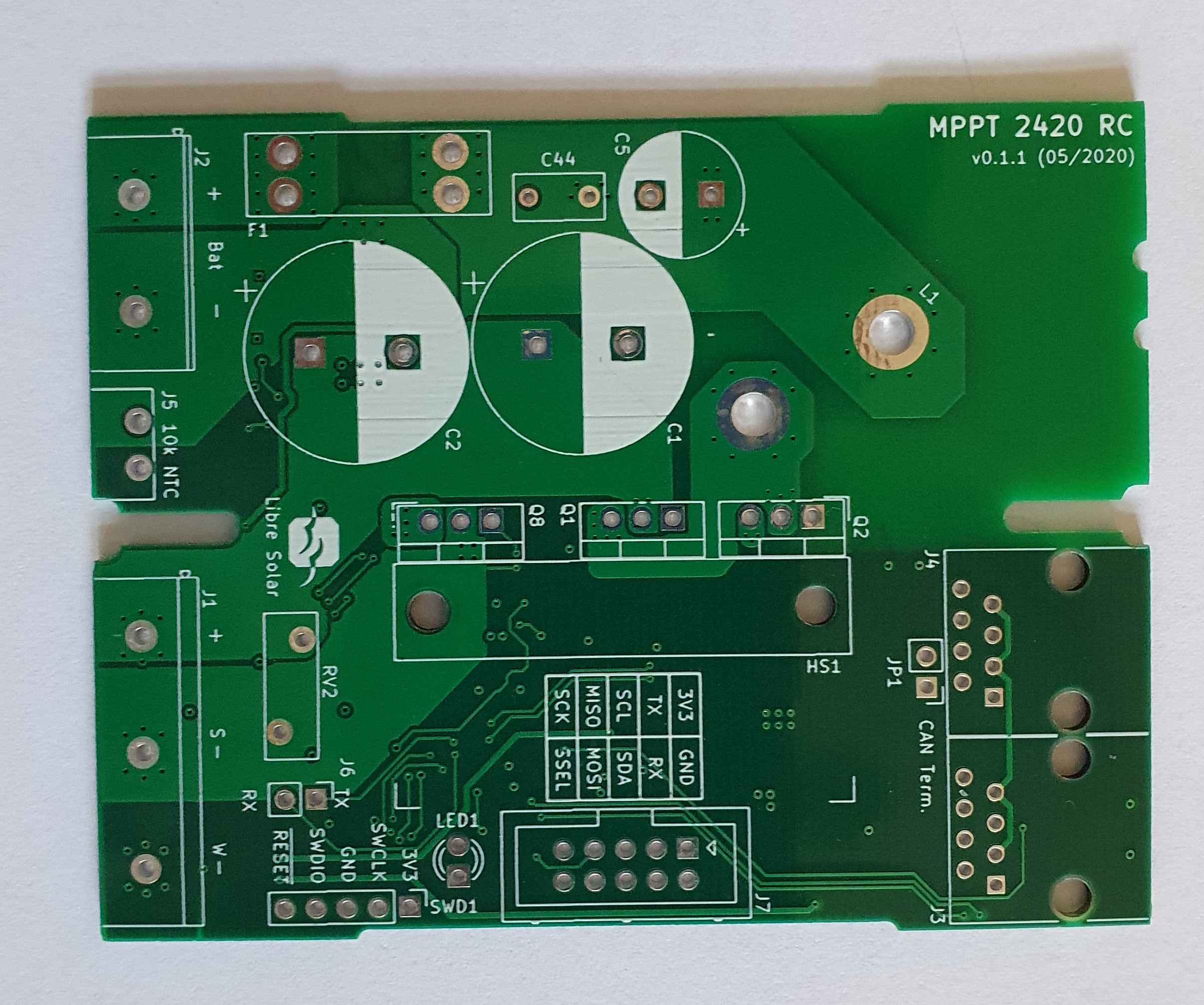
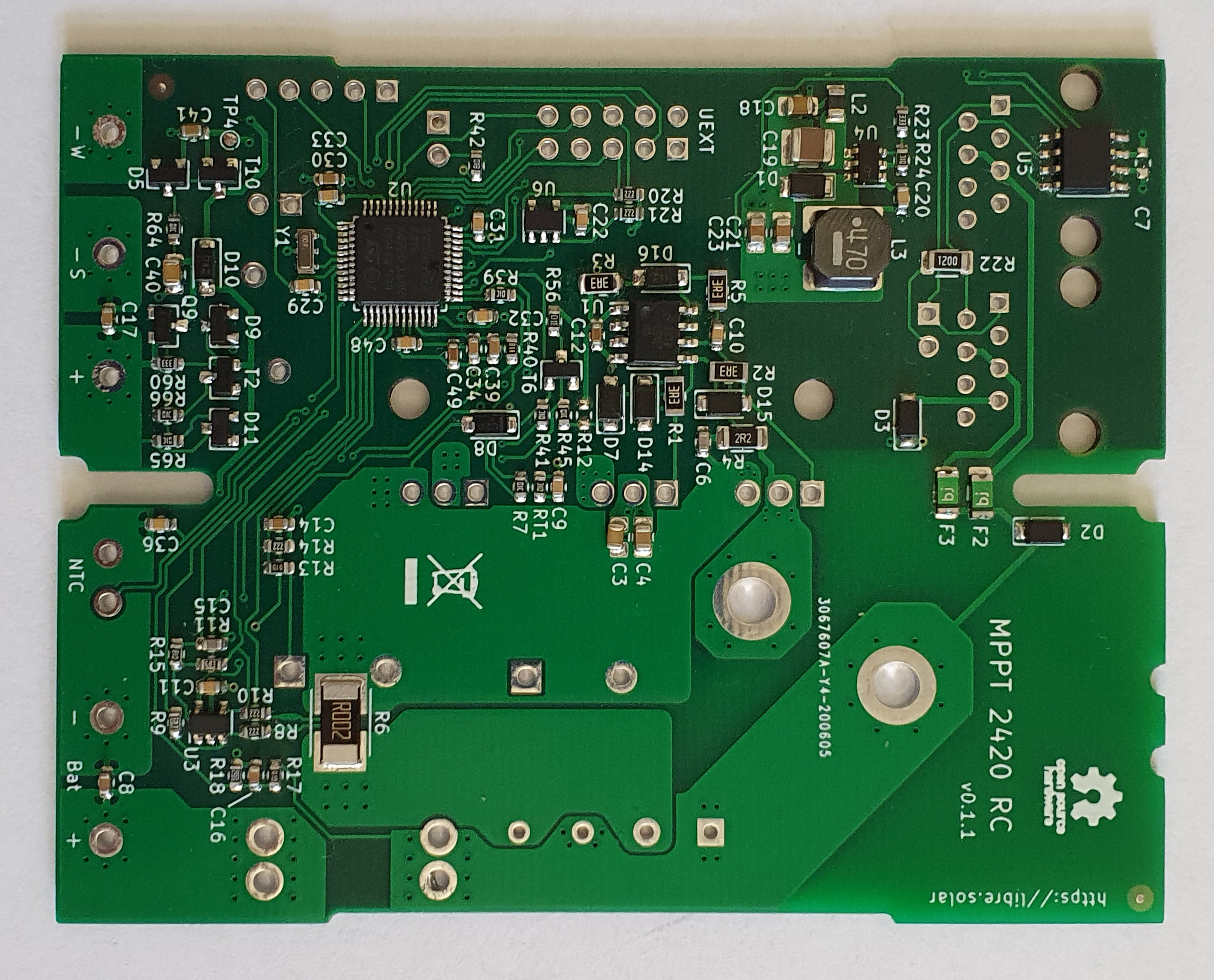
Here is a picture of MPPT-2420-RC board - top side:
I’ve made some preliminary test and found an issue with power supply from LV side (battery port)
With 12V everything works fine, but when I set voltage to 19-20V there is an unexpected increase of power consumption and diode D9 became very hot.
After some investigation I think that found the problem: voltage at base of T2 is fixed at 12V and when LV supply is increased above 12V, base-emitter junction became reverse biased and on some point (Vbe = -7V) starts conducting. This is normal because usually max reverse Vbe is around -5V.
My first solution was to replace T2 with NOMS MOSFET transistor (BSS138). In this case Vgs can go safely to -20V which gives 12+20 = 32V form battery port. Now PCB works fine with voltages above 19V volts. May be there is some more elegant solution, but now I’m going ahead with power parts of controller.
sorry for the late reply. I’m just coming back from vacation.
Thanks a lot for posting your findings. Your board soldering looks very good (better than my hand-soldering of the first board revision). Did you order it as an assembly from JLCPCB or did you reflow-solder it yourself?
The explanation of the identified issue makes sense. The solution with the NMOS looks good, but we would still have quite little margin to maximum voltage rating at the gate.
I also realized that the SMPS could “see” too high voltage if the input voltage is >60V and the battery is not (yet) connected.
I will think about a rework of this part of the circuit and post it here.
One more remark regarding this board: While testing the firmware I realized that the voltage readings are quite inaccurate (something like 0.5V lower measurement than actual voltage). It’s most probably a firmware issue, but I didn’t find a final solution yet. I pushed some preliminary changes to a separate branch stm32g4-adc-playground. Strange thing: This leads to improved accuracy with this board, but with worse readings in other board with the same MCU (MPPT 2420 HPX). That’s why I didn’t merge it to develop branch yet.
Thanks for your comments. I’m agree that solutions with NMOS is not optimal and hope there is more elegant way. The PCB is soldered by me using first DIY dispenser and vacuum tweezers and then reflowed by “upgraded” T962 smd oven. I can share more info if you are interested.
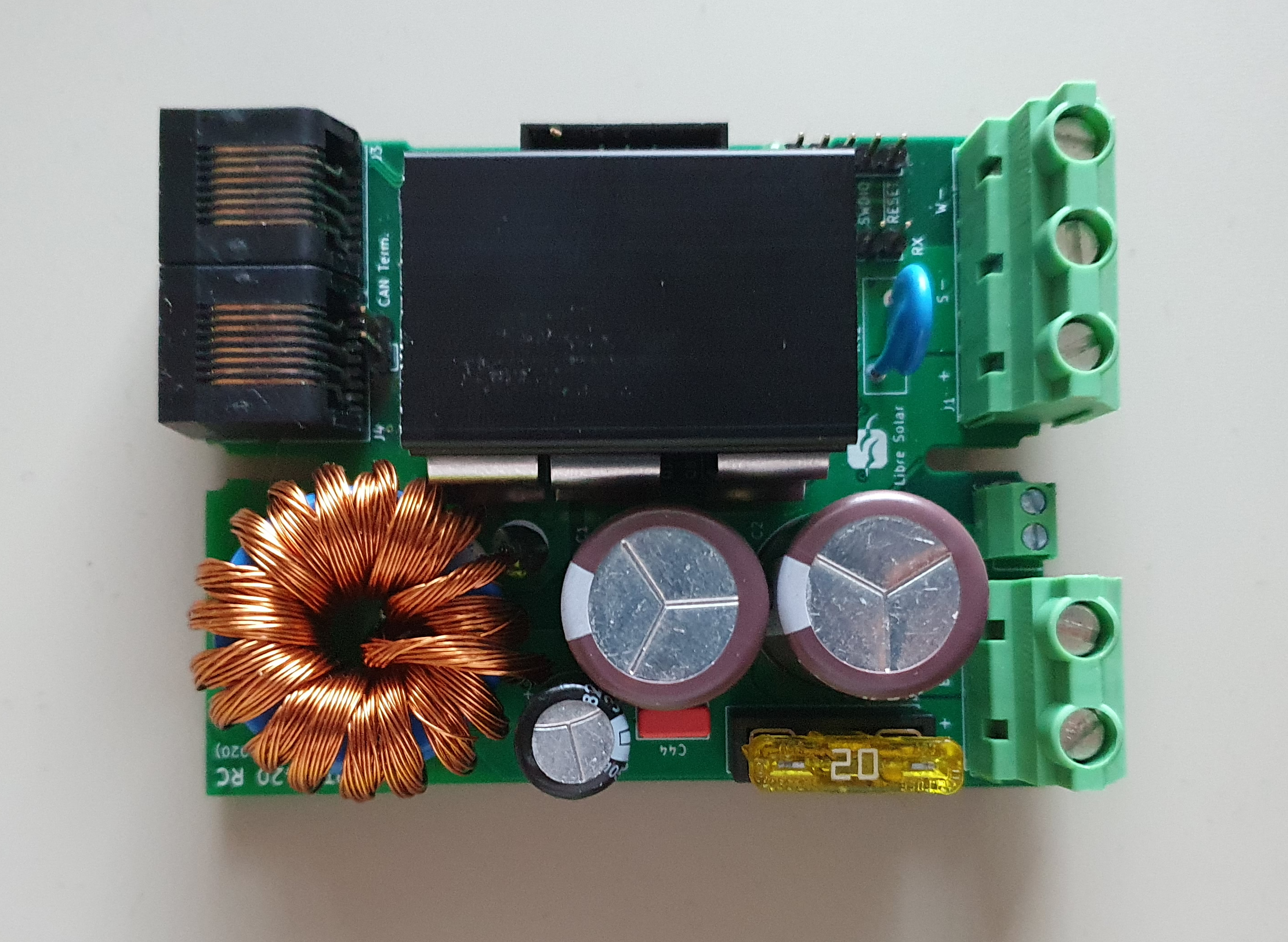
A picture of fully assembled controller:
Regarding Fischer heat sink I’ve found only 50mm size in Farnell, so I struggle a little bit to cut it to proper size. It’s a quite thick.
Now I’m ready to test firmware. I will consider mentioned issues. The external OA (U3) is populated and remembered this issue. Do I need to cut these wires?
I know the T962 oven. We’ve got the same in our fablab here (also upgraded with better temperature control).
Yes, you need to cut the wires as mentioned in the issue. For some reason the internal MCU pins influence the opamp behavior even if they are set to floating. Once you cut the wires, everything should be fine.
Started building firmware:
My build machine is Ubuntu 18.04 and I Installed Visual Studio Code and PlatformIO. Decided to checkout a master branch of Charge Controller Firmware.
Software build was successful, but upload failed - openocd can’t find “st_nucleo_g431rb” board.
Digging into the problem found that current version of openocd included in PlatformIO doesn’t support STM32G4. Indeed they are using a openocd-xpack release so I upgraded to the latest. The tool is located in ~/.platformio/packages/tool-openocd. Added a new file st_nucleo_g431rb.cfg in scripts/board with following lines:
Not very clean solution but now my STlink works with this board.
Then attached USB converter to debug console and uploaded firmware. Upload was successful, but nothing happened on console. Double checked pcb soldering, but everything looks fine, so started exploring software. I’m new to Zephyr framework and first decided to check config files, after some puzzling found that in file “Kconfig.defconfig” configuration for UART console is commented. Resotred it and changed to UART_2 (uart2 is on UEXT connector)
config UART_2
bool
default y
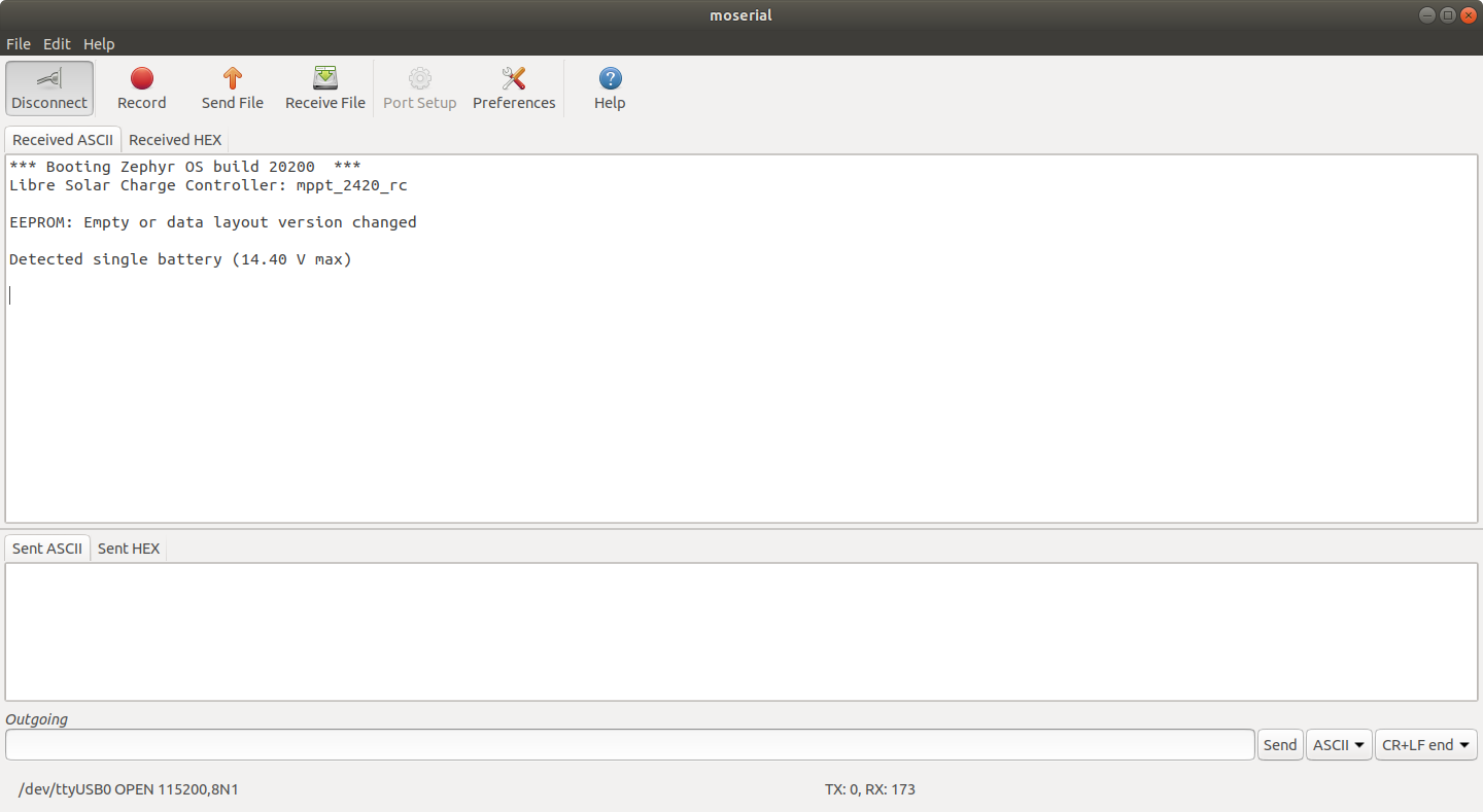
Clean up and recompile and voila charger is working and LED1 is on. Here is screenshot on console:
Sorry, I accidentally added some untested other stuff to the previous stm32g4-adc-playground branch, fixed that now. However, it’s force-pushed, so you may need to delete your local branch first before you can pull it.
The above branch is based on the develop branch, which has better support for this board. I will soon make a new release of the firmware and update the master with the stuff going on in the develop branch. But I need some further testing. The current master is still based on Zephyr v2.2.
Thanks for figuring out a solution to flash with OpenOCD. I was using Jlink for this MCU or west directly (which uses pyocd instead of OpenOCD). We should probably raise an issue to PlatformIO and ask if they can update their shipped OpenOCD version.
If something is not working just post it here. I have the same charge controller hooked up at my test bench at the moment, so we can fix things together
I’ve deleted project and started with new git clone, but still have problems with stm32g4-adc-playground branch. I think this is some how related with new version of Zephyr v2.3 and ststm32 platform release 7.1.1. Attached logs, may be I missing some step: console.log and CMakeError.log
Installed and tried via west according GitHub instruction but when I try:
You need to point west to the upstream Zephyr repository before you can run west. Under Linux the command is source path-to-your-local-zephyr-repo/zephyr-env.sh. After that you should be able to run west from within the charge-controller-firmware/zephyr directory (assuming the Zephyr SDK was installed according to Zephyr documentation).
From within the local Zephyr repository you can also change the Zephyr version by selecting a different branch from master (e.g. git checkout v2.3-branch). This is recommended as Zephyr master is changing quickly and might break compatibility otherwise.
Thanks for guidelines. I’ve installed Zephyr successful and now can build stm32g4-adc-playground branch. Building via PlatformIO remains broken for me and I noticed fresh installed Zephyr uses GCC version 9.2.0 (via zephyr-sdk-0.11.3) against v 8.2.1 in platformio. Native Zephyr build works fine including programming via pyocd, so I will stick on it.
I’ve found 2 issues while compiling firmware:
There was missing definition of COMMIT_HASH, and I have to run manually script file generate_version_file.py in order to fix this problem
First build of firmware crashes immediately after boot. After some investigation found that problem comes from CAN interface. In file mppt_2420_rc_defconfig CAN is enabled but in mppt_2420_rc.dts file CAN configuration is commented. (I’ve read this requires specific WIP driver to be installed). I fixed this by settings:
CONFIG_CAN=n
CONFIG_EXT_THINGSET_CAN=n
Now controller works and that is boot message:
*** Booting Zephyr OS build zephyr-v2.3.0-4-gc0d3c8004422 ***
Libre Solar Charge Controller: mppt_2420_rc
EEPROM: CRC of data not correct, expected 0x234caf59 (data_len = 227)
Detected single battery (14.40 V max)
I hope finally my build is against proper version of firmware and can start some real test despite limited setup: only small 3S Li-Ion battery (5Ah) and one DPS to simulate solar panel. I’ve done fast check of battery voltage:
?output [“Bat_V”]
:85 Content. [10.47]
But my multi-meter shows 10.03V and tomorrow will check this.
Martin, any comments are welcome.
The generate_version_file.py script is automatically called by platformio, so building via PlatformIO needs to run once before using native Zephyr build. But I found a way to generate the version via CMake (see latest commits in develop), so this issue should be resolved.
Good spot. Fixed that in the commit that added CAN bus support for this board and will enable it only after the mentioned PR has been merged to Zephyr master. (fixed with rebase in original commit, so you need to delete the branch again before pulling)
I made a quick additional test to check the the ADC inaccuracies:
Multimeter: 13.29 V
With ADC patch (stm32g4-adc-playground branch): 13.22 V
Without patch (develop branch): 12.67 V
Even with the patch the accuracy could be better, so there is still some research necessary. However, it’s strange that your charge controller measures a higher voltage than the multimeter… here it has always been other way round.
This is strange indeed…
Checked again hardware. Divider R17 and R18 is set correctly, and measured voltage at that point is 0.5316V with 10.037V at battery port. Reference is 2.0422V, so from hardware point of view things looks fine.
I hope tomorrow will have more time and check software configurations.
this error is caused by some fixed offset in ADC, around 50 LSB. I can see it on both input ports - LV & HV. On LV ports this translates to 0.45V measurement error and 1.16V on HV ports.
Found some strange behavior- if I short briefly resistor R18 this causes a lots of low/high voltage alerts on console, and charger is rebooted by wacthdog: “Watchdog channel 2 triggered!”
And then ADC measurements are OK I’m suspecting some calibration issue regarding ADC.
Despite this I can confirm that charger is working properly. I was able to start battery charging from HV port
That’s an interesting finding that it works after reset! And also that it’s a constant offset… this could mean that the self-calibration during startup doesn’t work well. Will check that out on Monday.
Yeah I am also suspecting that it’s a software issue. The ADC peripherals of STM microcontrollers usually perform very well.
I think found a possible reason for measurement offset - it’s somehow related to internal reference voltage start-up time. There is a bit VRR in register VREFBUF_CSR which indicates when buffer output reached the requested voltage. Taking this into account modified vref_setup() function:
LL_APB2_GRP1_EnableClock(LL_APB2_GRP1_PERIPH_SYSCFG);
LL_VREFBUF_SetVoltageScaling(LL_VREFBUF_VOLTAGE_SCALE0);
LL_VREFBUF_DisableHIZ();
LL_VREFBUF_Enable();
while (LL_VREFBUF_IsVREFReady() == 0) {;}
Now function waits for VRR bit to get ready. This improves situation with offset: around 40mV after POR, but now measured value is lower than actual. Console reset improves situation a little bit and offset drops to 20mV. May be there is another issue regarding ADC start-up/calibration and I’m not quite sure what ADC accuracy is achievable with this MCU, now it’s about 2-5 LSB.
@yasen Seems like your suggested waiting loop for stabilization of the voltage reference and some other small changes finally did the trick. I’m getting quite accurate readings now.
ADC input pin according to multimeter: 0.734 V
Voltage measured by ADC: 0.731 V


 I’m suspecting some calibration issue regarding ADC.