Nope, there are no published test results yet, as I’m still struggling with the firmware. Porting to the new MCU (including change to Zephyr OS) took more time than intended. The two ADCs are still not working well with DMA, so I couldn’t test the DC/DC power stage yet. Hope to get there till end of the week.
Other things like I2C communication with a display work fine. But that’s not most important, I guess
I’ve just seen that the new design is alpha-stage now. I like the highside switch and highside shunt. No flawn found so far. Same as at the MPPT 2420 charger before, i can offer emi analysis for the new design if wanted. Same as done at our c-turm, i can offer fieldtest for the new design. We plan to use the battery powered solar system in summer for ham radio activity again. So we can compare the emi behaviour directly between old MPPT 2420 and new design. Old design had emi-issues in 2m radio wavelength range.
Yeah the good news is that I just tested the high-side switch and the charge pump successfully. The charge pump is working well, so the LT spice simulation made before making the schematic did a good job.
I’d be happy to do some testing regarding EMI. It should be much better than the previous 20A charge controller, as I included some learnings from previous design and testing in the board layout. In the summer the design should be fully working and I should have some more boards available.
I will probably update the design a bit and include the RJ45 ports for CAN bus directly on the board again. And if I find some hardware bugs during ongoing testing, they will be fixed aswell, of course.
thank you very much for sharing your MPPT charger design.
I really appreciate that you would like to include the CAN Bus directly on the Board.
Have you already thought about which pinout you will use?
I mean like canopen or something?
Did you also think about the Transceiver that will be build into your design?
Needs to be Durable and modular? not compact, not the smallest components but larger rather.
MPPT BMS should be same size stackable taking into account heat sink mounting and display position?
Do you think paralleling with more Mosfets for current sharing might be a good thing to reduce the heat dissipation. Has the heat dissipation on the Mosfets improved with the the new design of mppt-2420-hpx.
Multiple MOSFETs for current sharing create issues with the PCB layout as it’s impossible to place them all very close to each other to prevent large loops with high di/dt. The better solution would be to create a dual-phase converter with 180° phase shift, which also reduces the current ripple on the capacitors. However, you also need a second inductor.
With the MPPT-2420-HPX you can screw the MOSFETs to a large heat sink, so there should not be any issues at all depending on the heat sink size. I’m currently testing without heat sink in order to get better accessibility to the pins for snubber layout etc. When that’s finished, I will mount it to a heat sink and do further tests.
The Q8 Mosfet which works as PV reverse current protection needs to be turned on for measuring the High Side Voltage. So during night we are back powering the solar panels if they are connected at the HV side every time we measure the High side voltage.
Will this damage the solar panels. What do we do to mitigate this issue.
You don’t need to switch on Q8 for measuring the PV module voltage. If you keep it off, the measured voltage will have an offset of the body diode drop of Q8. But that’s not an issue as you only want to detect if the panel voltage is at least a few volts higher than the battery voltage.
Thank you very much for sharing your MPPT charger project!
I have a small set-up 290W solar panel and 8S- 40Ah LiFePO4 and this charger fits well.
So I’m planning to build one, make tests and contribute to project. I’m not afraid of pcb soldering so first step is to get a pcb for current design. Do you have any spare pcb left from previous run?
Meanwhile I’ve checked design wih JLCPCB and their offer is around 65$ for 5 PCB including shipping and taxes to my location (Sofia,BG) (or 10 PCB for 75$) Their 4 layer layout stack is based on 35um/17um/17um/35um cooper thickness. Do you think it is OK for current MPPT design?
It’ me again.
I’ve just saw a new MPPT 2420 RC charger on GitHub. It looks great and has a more compact form factor. I definitely go for it. Can you tell us what is current status of the design?
I built the first MPPT 2420 HPX board also with a 35um outer layer. It’s does work, but is certainly not ideal for 20A.
For prototypes I can generally recommend aisler.net for PCB manufacturing. They offer good quality PCBs with quite fast shipping at a similar price point. But unfortunately also not with larger copper thickness.
Regarding the status of the PCBs:
I’ve done quite a few tests with the HPX version and made some resistor value updates, but still need to update the repo. Most important functions of the PCB have been tested and are working. But I realized that got a bit too complicated, trying to cover all possible applications.
That’s why I played around with a more modular concept. The MPPT 2420 RC is mainly to test if the heat dissipation inside a DIN rail housing is sufficient for a 20A charge controller and if the integrated OpAmp of the STM32G431 performs well. Didn’t get the internal OpAmp peripheral running (most probably firmware issue), but apart from that the PCB should work aswell (you can populate the external opamp).
I decided to publish also work-in-progress PCBs (and mark them accordingly) as they may still be useful for other people. However, depending on the results of the full load tests I might not go ahead with the DIN rail housing concept.
I’ve decide to go with MPPT-2420-RC, despite work in progress status. I liked it’s modular and clean design.
Aisler PCB service looks very attractive and I definitely try it soon. Now I’ve decided to try JLCPCB and now expecting some pcb for MPPT-2420-RC and BMS-8S50-ic projects. Both ordered on 35um cooper, but I’m not planning to go over 10 A. I hope that can get them in two weeks and begin soldering Meanwhile I’ve started collecting BOM parts and reading docs about projects.
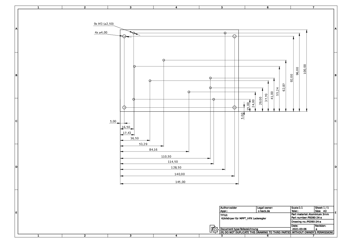
Just for information. I build 5 units MPPT-2420_HPX. I know the design is outdated, but i have PCBs and do not want to discard them. First unit is running, needed to change R14 to 2.2k, so it suits to software.
If someone wants to build a unit, i made a drawing for the cooling plate drilling.
Hello everybody I am new here. First of all I would like to thank Martin for designing & releasing this MPPT charger as open-source.
IMO the main feature that’s still missing from the current 2420-HC design is 48V battery support.
48V battery support goes a long way in increasing real world utility of this charger.
I looked at Martin’s previous reply to this suggestion and all the problems listed seem solvable to me.
Replace MOSFETs
Why? The current MOSFETs (IPA045N10N3G) are rated for 100V which seems quite enought for a 48v LV design (max charge voltage for li-ion is ~55v).
AFAIK MOSFETs limit high side voltage (80v).
INA186 LV current sense amplifier common-mode voltage (Vcm) is 40v max. (for proper 48v design Vcm should be at least 60v)
First I wanted to replace the amplifier entirely for one with sufficient Vcm (e.g. MPQ8112 or INA168),
but I realised there is not eneough space on that part of PCB to shuffle components (especially since INA186 is SC70 package).
Another solution is to put a 50% resistor voltage divider to the inputs of amplifier, this will double max Vcm.
10Ω resistors R8 & R9 can be replaced by much higher value (~10kΩ) and low tolerance (±0.05%) + another connected to ground.
However higher values of these resistors (they need to be high since we are connecting LV directly to the ground) will increase static gain error of the amplifier (page 21 of INA186 datasheet)
from 0.00047% to ~0.25%, but since the gain error is static (as far as I understand) it can be compensated for in firmware.
replacement resistors: https://www.digikey.com/en/products/detail/yageo/RT0603WRE079K1L/5931015
I would also consider raising max input voltage to atleast 85 volts, because most of ~450w PV panels have max Voc juust obove 40v
and it’s essential to bo able to connect 2 in series for proper 48v 1kw system. (15v safety margin for MOSFETs & HV caps seems sufficient)
Please let me know if the solutions I listed make sense and/or if I overlooked something important, I’ll start testing & putting together a prototype.
Yes, could be enough. But it would be nice to have slightly higher input voltage. Typical 48V charge controllers from other manufacturers often allow 150V.
Unfortunately, those are AC fuses. DC at 48V can create arcs when disconnected (which are extinguished in the case of AC because the voltage goes through 0V every few milliseconds). So we would need special fuses. They are available (e.g. from Littelfuse for fork lifter applications), but not as cheap and easy to get as automotive blade fuses.
Would be interesting to see which fuses Victron uses for their lower current 48V charge controllers…
Your suggestion for the voltage divider for the current sense amplifier sounds interesting, but as we are dealing with really small voltage differences here, I somehow doubt that we will get a precise measurement over different temperatures and accross different devices (even if it’s calibrated in firmware). I’d be happy to be proven wrong
Luckily, the STM32 micros seem to be in stock again.
For an improved design, I would actually suggest to switch to the STM32G0B1, which has more flash + RAM at lower price. Larger flash allows for easier firmware upgrades over CAN. Don’t think we need the higher processing speed of the STM32G4 series, but there was no STM32G0 available with CAN bus support at the time I designed the PCB.
So after some consideration I decided it would be less work to just fit MPQ8112 in palce of INA186.
You’re propably right about unstable measurments with changing temperature, and since accurate current measurment is instrumental in proper function of MPPT
it would be headache trying to debug unstable/unoptimal power output because of those resisotors.
MPQ8112 has the same current gain error as INA186, but gain multiplier is 50 instead of 25.
(SOT-23 package is not as big as I thought when I imported it to KiCAD PCB design)

 Meanwhile I’ve started collecting BOM parts and reading docs about projects.