It’ me again.
I’ve just saw a new MPPT 2420 RC charger on GitHub. It looks great and has a more compact form factor. I definitely go for it. Can you tell us what is current status of the design?
Yasen
It’ me again.
I’ve just saw a new MPPT 2420 RC charger on GitHub. It looks great and has a more compact form factor. I definitely go for it. Can you tell us what is current status of the design?
Yasen
Hey Yasen,
I built the first MPPT 2420 HPX board also with a 35um outer layer. It’s does work, but is certainly not ideal for 20A.
For prototypes I can generally recommend aisler.net for PCB manufacturing. They offer good quality PCBs with quite fast shipping at a similar price point. But unfortunately also not with larger copper thickness.
Regarding the status of the PCBs:
I’ve done quite a few tests with the HPX version and made some resistor value updates, but still need to update the repo. Most important functions of the PCB have been tested and are working. But I realized that got a bit too complicated, trying to cover all possible applications.
That’s why I played around with a more modular concept. The MPPT 2420 RC is mainly to test if the heat dissipation inside a DIN rail housing is sufficient for a 20A charge controller and if the integrated OpAmp of the STM32G431 performs well. Didn’t get the internal OpAmp peripheral running (most probably firmware issue), but apart from that the PCB should work aswell (you can populate the external opamp).
I decided to publish also work-in-progress PCBs (and mark them accordingly) as they may still be useful for other people. However, depending on the results of the full load tests I might not go ahead with the DIN rail housing concept.
Cheers,
Martin
Thanks for clarifications!
I’ve decide to go with MPPT-2420-RC, despite work in progress status. I liked it’s modular and clean design.
Aisler PCB service looks very attractive and I definitely try it soon. Now I’ve decided to try JLCPCB and now expecting some pcb for MPPT-2420-RC and BMS-8S50-ic projects. Both ordered on 35um cooper, but I’m not planning to go over 10 A. I hope that can get them in two weeks and begin soldering  Meanwhile I’ve started collecting BOM parts and reading docs about projects.
Cheers,
Yasen
HI Yasen, have you completed that pcb? i tried to order smt assembled but I can not find CPL file? can you find?
Hello, just published the new MPPT 2420 HC, which is taking the best of all previous 20A board designs:
It’s also already supported by the firmware, where I just updated the master
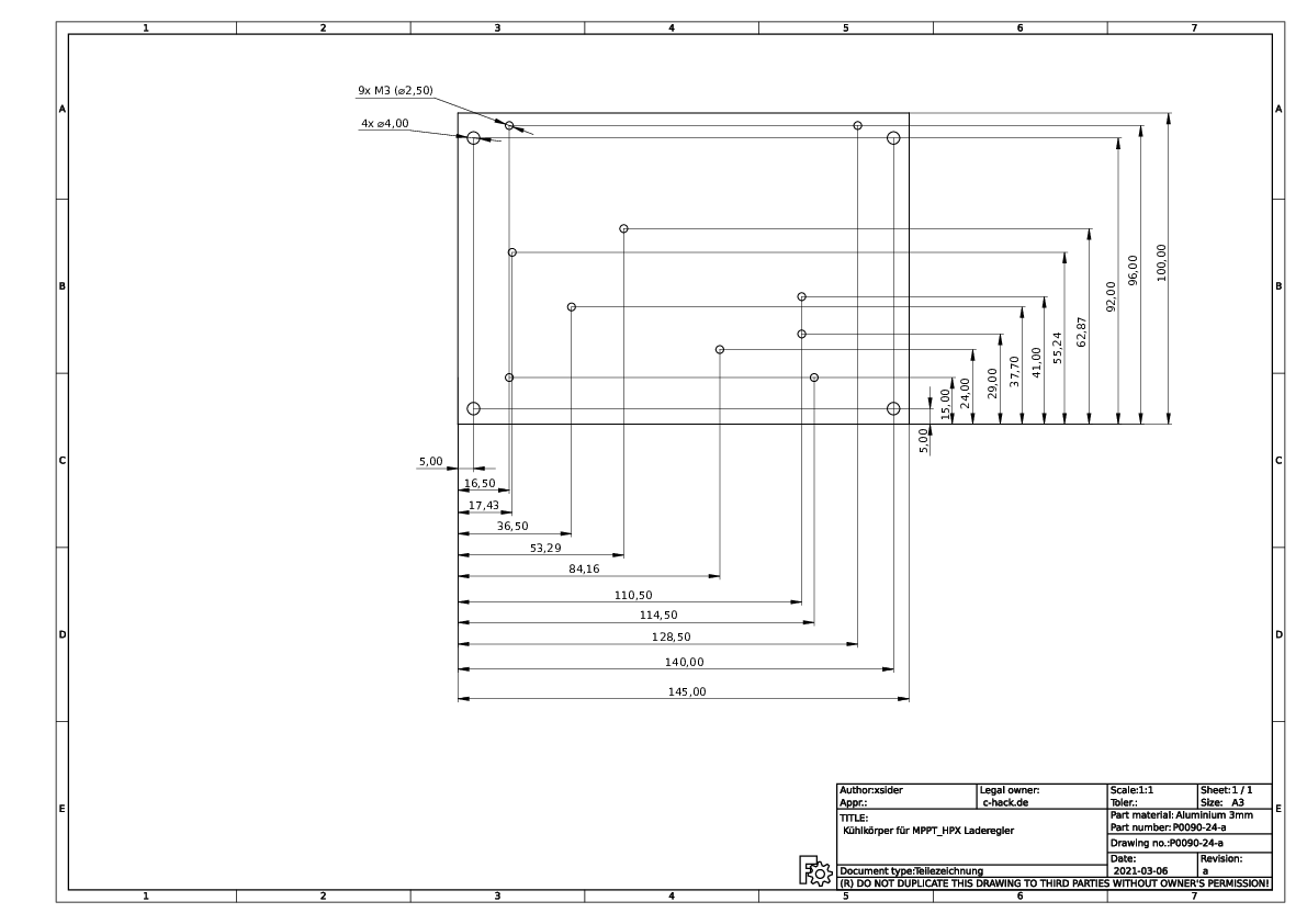
Just for information. I build 5 units MPPT-2420_HPX. I know the design is outdated, but i have PCBs and do not want to discard them. First unit is running, needed to change R14 to 2.2k, so it suits to software.
If someone wants to build a unit, i made a drawing for the cooling plate drilling.
Hello everybody I am new here. First of all I would like to thank Martin for designing & releasing this MPPT charger as open-source.
IMO the main feature that’s still missing from the current 2420-HC design is 48V battery support.
48V battery support goes a long way in increasing real world utility of this charger.
I looked at Martin’s previous reply to this suggestion and all the problems listed seem solvable to me.
Replace MOSFETs
Replace LV capacitors:
Replace automotive fuse:
Remove option for for HV supply voltage
INA186 LV current sense amplifier common-mode voltage (Vcm) is 40v max. (for proper 48v design Vcm should be at least 60v)
I would also consider raising max input voltage to atleast 85 volts, because most of ~450w PV panels have max Voc juust obove 40v
and it’s essential to bo able to connect 2 in series for proper 48v 1kw system. (15v safety margin for MOSFETs & HV caps seems sufficient)
Please let me know if the solutions I listed make sense and/or if I overlooked something important, I’ll start testing & putting together a prototype.
Yes, could be enough. But it would be nice to have slightly higher input voltage. Typical 48V charge controllers from other manufacturers often allow 150V.
Unfortunately, those are AC fuses. DC at 48V can create arcs when disconnected (which are extinguished in the case of AC because the voltage goes through 0V every few milliseconds). So we would need special fuses. They are available (e.g. from Littelfuse for fork lifter applications), but not as cheap and easy to get as automotive blade fuses.
Would be interesting to see which fuses Victron uses for their lower current 48V charge controllers…
Your suggestion for the voltage divider for the current sense amplifier sounds interesting, but as we are dealing with really small voltage differences here, I somehow doubt that we will get a precise measurement over different temperatures and accross different devices (even if it’s calibrated in firmware). I’d be happy to be proven wrong ![]()
Luckily, the STM32 micros seem to be in stock again.
For an improved design, I would actually suggest to switch to the STM32G0B1, which has more flash + RAM at lower price. Larger flash allows for easier firmware upgrades over CAN. Don’t think we need the higher processing speed of the STM32G4 series, but there was no STM32G0 available with CAN bus support at the time I designed the PCB.
So after some consideration I decided it would be less work to just fit MPQ8112 in palce of INA186.
You’re propably right about unstable measurments with changing temperature, and since accurate current measurment is instrumental in proper function of MPPT
it would be headache trying to debug unstable/unoptimal power output because of those resisotors.
MPQ8112 has the same current gain error as INA186, but gain multiplier is 50 instead of 25.
(SOT-23 package is not as big as I thought when I imported it to KiCAD PCB design)
You’re absolutely right, you cannot use 5x20mm glass fuse for DC.
Best alternative I’ve found is to use 6.3x32mm ceramic fuse rated for 63V DC.
(e.g. https://www.digikey.com/en/products/detail/schurter-inc/8020-5024/6568976)
This fuse however won’t fit in place of current keystone fuse holder, and there’s no space to push component out of the way (mainly LV caps).
My workaround is to solder ~12AWG wire in the holes of current fuse holder, with external fuse holder like this (It will be janky but functional :D)
https://4donline.ihs.com/images/VipMasterIC/IC/LFSI/LFSI-S-A0001354937/LFSI-S-A0001354937-1.pdf?hkey=6D3A4C79FDBF58556ACFDE234799DDF0
I will soon have commit ready, we can create 48v dev branch in github repos (both hw and firmware).
If you want to use 5x20mm-fuses, there are DC-rated fuses, for example ESKA PF-WN20 (https://www.eska-fuses.de/fileadmin/produkte/datenblaetter/ESKA-PowerFuse.pdf)
For me, i prefered blade-fuses (MegaOTO) for 32V DCmax-circuits, which can be screwed directly into thick cable wire systems, and HV-Solar-fuses (10.3x38mm 1000VDC) for higher voltages and circuit breakers where i prefer more safety. The smaller fuses have maybe enough DC circutit breaker voltage capability (400-500V) but they lack of possible short circuit breaker capability.
The megaOTO-Fuses are avialable for 70VDC also, so should fit your battery needs?
I connect them directly on battery pack, or at the line through the solar panel, for any kind of backward current flown maybe.
Hi,
i like to join this rebuild activity.
What charge controller you are talking about?
I am interested in:
Is there a github branch for this optimization/rebuild?
I can do: sw (stm32,esp32), hw (kicad).
My setup is made of PWM2420LUS and MPPT2420LC (obsolete design with emi-issues). My plan is to change the PWM-chargers with MPPT chargers MPPT1210 at 2023. I use 12V and 24V setups with BMS15S80SC and BMS5S50SC (both obsolete). I think for things-to-do [Martin] is the main actor. If you have an improvement make a pull request to the existing git projects?
Ok, so I have finished first 48v prototype design of the board + firmware
with all the previously discussed changes. (see commit messages and diffs for details)
hardware repo fork: GitHub - codin2odin/mppt-4820-hc: MPPT charge controller with HS load switch and CAN bus
firmware repo fork: GitHub - codin2odin/charge-controller-firmware: Firmware for Libre Solar MPPT/PWM charge controllers
In hardware I have changed current sense ic (MPQ8112) amp !only! in DC/DC (battery) circuit.
I don’t plan to use/populate load terminal of the board. (my design is classic PV/wind->mppt->battery->inverter system)
Before building first prototype, load terminal circuit current sense amp ic should be also updated.
(OR remove load terminal circuit from the design altogether & implement standalone PWM module for batteries if someone wants to use DC load, this will reduce costs for each mppt board)
I also raised max input Volatge to 85V (see my previous post why, both MOSFET & HV caps are rated 100V so should be safe).
Unfortunately I have only found 20A 60V DC 5x20mm fuses in eska catalogues (with conflicting info), and haven’t found anywhere to actually buy them.
I’m sticking to my orginal suggestion of 6.3x32mm dc ceramic fuse with inline fuse holder.
Added mppt-4820-hc board directory & changed i-dcdc pin multiplier from 25->50 in .dts file. (see MPQ8112 datasheet)
As far as I understand for 48V LV firmware support we only need to properly set ‘CONFIG_BAT_NUM_CELLS’ & ‘CONFIG_BAT_TYPE_???’ in app/prj.conf file during build (I could be wrong).
I am not experienced embedded C++/Zephyr developer so more eyes on the code would be appreciated.
That sounds very exciting. I can definitely support with getting your board setup ready in Zephyr. That should be the most easy part of the 48V MPPT. And yes, I think it should work just with adjustment of CONFIG_BAT_NUM_CELLS.
I’m quite busy with other stuff at the moment, but I’ll try to have a look at the hardware as soon as possible.
Hi digital_mage,
i like to join your activity.
I can do:
What is the minimal layer thickness?
With some cheap PCB manufacturers,
the default/cheap inner thickness is 0.5oz
and the outer thickness is 1oz.
Changing this to 2oz/1oz quads the price.
Is this really necessary?
Maik
Hello Maik, thanks for offering help. I can handle hw side of the project for now, but I could use help with modifying firmware.
Old current sense amp (INA186) also had REF voltage applied to it on pin 1 (DAC1 pin from MCU), to which it added sensed volatge.
You could figure out what voltage was DAC1 pin outputting & remove this REF voltage from DCDC current calculation in firmware.
I absolutely wouldn’t mess around with copper layer thickness, this board have to be able to handle 20A of current, which means top signal layer & GND layer HAVE to have minimum 0.035mm copper thickness.
Hi,
thank you for the answer.
Do you have got a PCB left. I like to buy one.
Otherwise, i would order a bunch of 5 PCBs with the current layout.
How far you are with the changes.
I will check how PA4/DAC1 is used by the firmware.
Where you are located. I am from germany/hannover.
static void dac_setup()
{
#if defined(CONFIG_SOC_SERIES_STM32F0X) || defined(CONFIG_SOC_SERIES_STM32L0X)
…
#elif defined(CONFIG_SOC_SERIES_STM32G4X)
LL_AHB2_GRP1_EnableClock(LL_AHB2_GRP1_PERIPH_DAC1);
/* DAC1 at PA4 for bi-directional DC/DC current measurement at 0.5 * VCC /
LL_DAC_SetOutputBuffer(DAC1, LL_DAC_CHANNEL_1, LL_DAC_OUTPUT_BUFFER_ENABLE);
LL_DAC_Enable(DAC1, LL_DAC_CHANNEL_1);
LL_DAC_ConvertData12RightAligned(DAC1, LL_DAC_CHANNEL_1, 4096 / 2);
/ DAC1 at PA5 for uni-directional PWM and load current measurement at 0.1 * VCC */
LL_DAC_SetOutputBuffer(DAC1, LL_DAC_CHANNEL_2, LL_DAC_OUTPUT_BUFFER_ENABLE);
LL_DAC_Enable(DAC1, LL_DAC_CHANNEL_2);
LL_DAC_ConvertData12RightAligned(DAC1, LL_DAC_CHANNEL_2, 4096 / 10);
#endif
}
On init, DAC1/PA4 is set to 0.5*VCC = 3.3V/2
Couldn’t and further use/change of DAC1.
Not sure why, DAC/2/PA5 is set to 0.1*VCC
That’s in order to have larger range of the current measurement voltage output signal (compared to the bi-directional measurement), but still avoid saturation at 0 current, so the setpoint is slightly above zero.
I am new here, It will be nice if the design was to expand the system capacity below i.e
150V PV Max input
80A Max current
Auto Select Battery voltage from (12v-96v)
5000W max
What can be done to achieve that ?