Hello everybody,
I have been unsuccessful in my attempts to build the firmware for the MPPT 2420 HC for some time now and am at my wits end. I am sure it is a layer 8 issue, since I am new to Software Engineering in general. I hope more experienced members can point out where I went wrong. I have attempted to build the firmware using Visual Studio Code with PlatformIO.
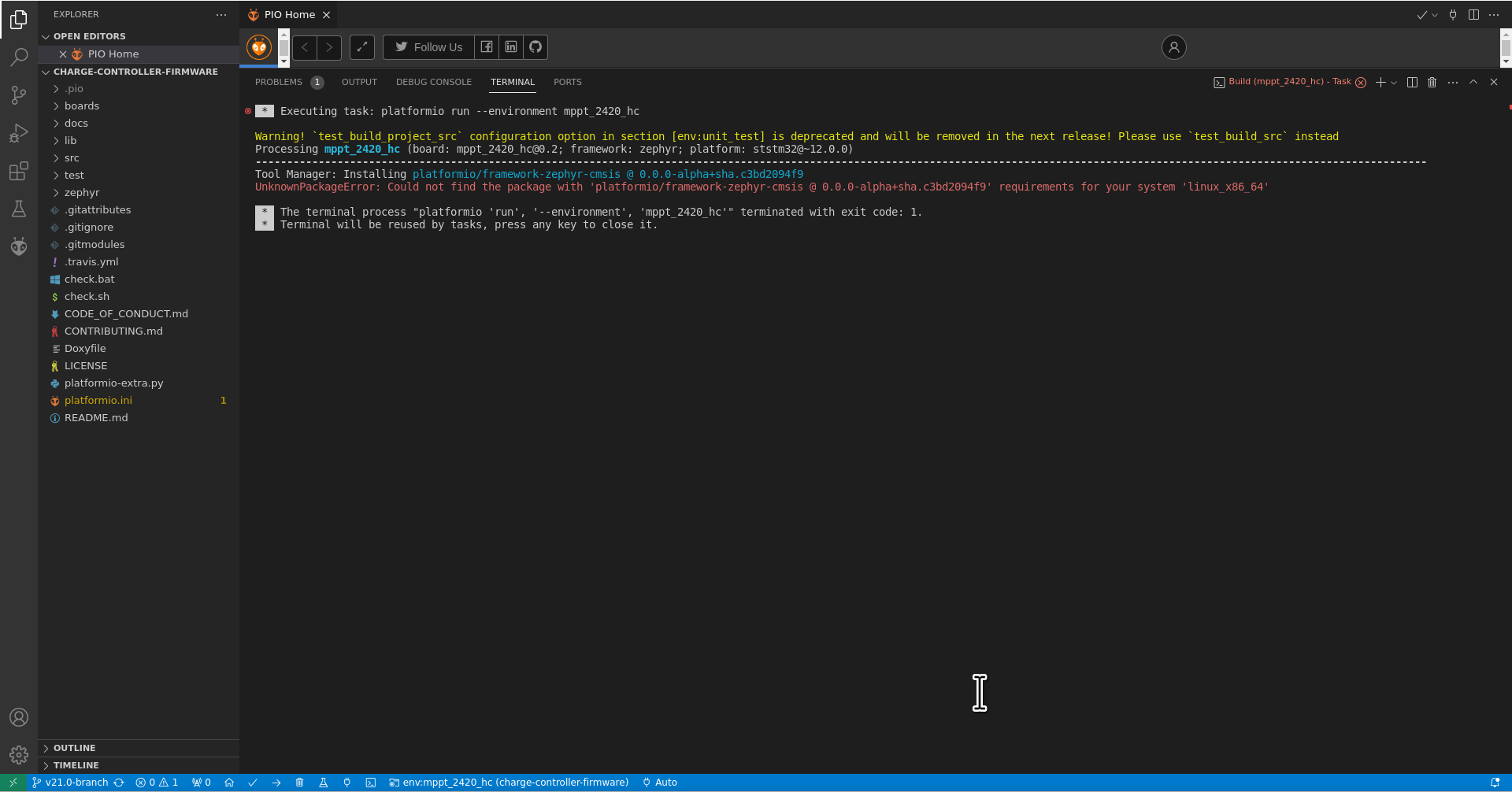
My first issue was, that the main branch of the repository doesn’t contain a platformio.ini file. So I switched to “v21.0-branch”, where I found the file. However, when attempting to build the project I ran into the following error:
I already tried to delete the .platformio directory and reinstall PIO, to no avail.
I use Debian Bullseye Backports.
If anyone has any idea, what else I can try I would be forever grateful!
Hi @SJM_LIB,
unfortunately, PlatformIO does not support recent Zephyr anymore, that’s why we dropped support in the charge controller firmware.
I’m not sure what the reason for your error may be, so I can only suggest to use the original Zephyr SDK.
Hi @martinjaeger ,
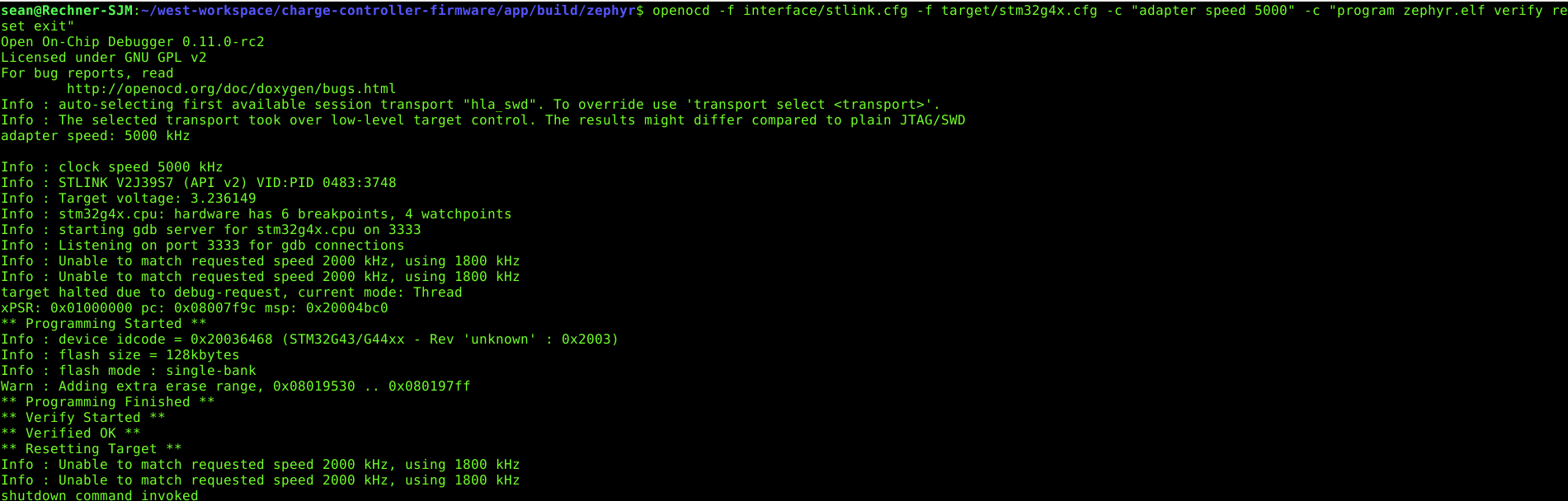
thanks for the swift reply! I managed to build the software with Zephyr SDK, however I could not flash it using west (pyOCD didnt recognize the specified target). So I tried using OpenOCD without west with the following result:
UPDATE:
It was just layer 8 error  I set some permissions wrong for Putty and it couldnt open the Serial Monitor. Finally I can begin testing!
Great! Happy to hear that. Let us know if you have any other difficulties.
Hey there,
I managed to get the Charge Controller up and running. I don’t have any real difficulties in the matter of it not working, however I am a bit stuck.
I want to use it a a boost converter, so I changed the config to Solar at LV and battery at HV and changed the battery type to NMC 14s. On my first try, I connected my E-Bike battery right away and got a bridge short circuit and fried some things after turning it on. Not quite sure yet how that happened, perhaps a bad config on my part.
After repairing the charge controller I checked the PWM waveforms and deadtime and it seems ok(around 300 ns deadtime). Also I checked the FET driver output and it was fine (at least the lowside. I didn’t have any FETs soldered on during that time so of course bootstrapping didn’t work and I couldn’t check the HS output).
Then I decided to disconnect the PWM input to the highside FET and ground it permanently and only use the low side FET, basically using the high side body diode as a switch. As a load I use an electronic sink in CV mode in parallel to a power supply with a minimal amount of output current to trigger the charging process. As an input I use a different power supply. For now it is working as expected, producing 48 V at the output. However it keeps increasing output power to the point where my power supply cant supply enough current and the charge controller shuts off due to LV undervoltage relatively quickly.
Now of course I could connect a beefier power supply or a battery, but I don’t want to fry things again. So I will wait until I understand the device thoroughly enough.
The documentation states, that there is a state for the DCDC with CC at the HV side. I would like to enter that state and also set the current limit. I checked the files dcdc.h and .cpp and found the declaration and definition of the responsible functions, but not really a way to make the charge controller enter the state. Also I didn’t find a way to set the current limit for this state.
I am a bloody beginner at programing and it is a bit difficult for me to understand the code out of the box. Perhaps you could offer some guidance on how to configure the software in the way I described? That would be muuuch appreciated. Thanks!
You should probably just limit the hv_terminal’s pos_current_limit and neg_current_limit to make it work. I guess you don’t reach the default current limit with the current-limited power supply, yet.
What kind of toolchain do you use for debugging? If I use Zephyr SDK I can’t flash or debug because PyOCD ist selected as standard, but its missing the config files for the target. My workaround was building via west and flashing manually using OpenOCD. However I am not able to debug that way and have gotten to the point where I really need to debug.
From what I understand about the code, the current limit is set in correspondence to the specified battery capacity in Ah. I set the capacity to 10 Ah, though I am not sure if that corresponds to 10 A. I got a little beefier power supply and set the limit to 12 A. Still the charge controller still keeps drawing more current until my supply goes to CC mode and the voltage starts to drop. However before the LV voltage can drop below 9 V to trigger the low power shutoff, it already shuts off after 10 seconds with the low power warning. Even though it is currently drawing about 120 W <. From what I’ve seen in the code this should only happen if the output power is > 1 W.
So either current measurement or voltage measurement is not working properly. But all the signals appear to be correct. So I want to display the ADC values during runtime.
Another strange thing is, that there is an offset on the HV terminal voltage of about 6-7 V compared to the real value. The displayed value is lower. Finally the MPPT isn’t drawing more than 0.9 A if the number of cells is below 12 and then still goes into low power shutoff after 10 seconds.
Do you have some advice?
I’m usually debugging with a Segger J-Link and Ozone, as this just works all of the time. However, I did also get OpenOCD to run in VS Code.
You can use OpenOCD for flashing and debugging with west by specifying the runner argument (e.g. west flash -r openocd). You may need a recent version of OpenOCD for the STM32G4 to work properly. See here for the runner configuration:
The default current limit based on the capacity is just a guess and should be overwritten via ThingSet if you have proper information about your battery available.
The offset in the HV terminal voltage sounds strange. Can’t remember I ever had this issue.
The low power shut-off algorithm did have some issues in the past, depending on the setup, but we didn’t have a good idea how to detect when to switch off the DC/DC in a different way. It tends to work better with real solar panels than with a power supply.
Thanks for the quick answer!
Then I will learn ThingSet and try to set the current that way.
I actually managed to get pyOCD working by installing the target. So flashing and debugging using west works now(at least I can access gdb over the command line).
However now UART1 only displays “E: can’t read core clock” twice and the program runs no further. Upon Reset, the same thing happens. I’m guessing core clock refers to the oscillator? Pin 6 of the µC (PF1-OSC-OUT) is not really doing anything. It should be at a level of around 1.8 V right? It’s currently sitting at 0.02 V. I am a bit confused, as I haven’t changed anything. Still I checked all the connections and they seem to be fine.