Hi @szmolnar. Sorry for not being very responsive. I’m currently in Rwanda for a solar project and quite busy.
Yeah, the STM32L0 a bit annoying. There seems to be an issue in OpenOCD which makes flashing fail sometimes. I could not find the perfect solution yet, see also here and here. However, with the original ST software or with Segger debug probes it works fine.
It might actually be possible that the new 20A MPPT design supports your setup with LED boost converter with a few tweaks. I’ll have to double-check. And I will try to upload a first design before Christmas.
Hi Martin!
that sounds promising, I’m really curios for the first design!
If you really want to implement the LED driving feature I will prepare some notes for you with all the LED lighting features I’m already using in my other designs.
Also thanks for the OpenOCD info and have a great time in Rwanda! 
As mentioned in the other thread, I uploaded the new design.
Unfortunately I think that your LED application is not yet possible, but it might be with a small modification. If we make Q8 controllable with an extra GPIO, we could connect the solar panel to the MPPT port and the LED to MPPT port positive and PWM port negative. Do you think that could work? If yes, I could make Q8 controllable for the next revision.
Hallo Martin!
If I understood you correctly your plan is to:
- Connect the PV to DCDC_HV+ and DCDC_HV-
- Connect the LED to DCDC_HV+ and PWM_SW-
- Q8 is controlled by the LM5107 Mosfet driver, but you want to control it’s gate from a GPIO so that Q8 can disconnect the PV from the DC-DC converter while it is in boost mode.
I had not much time but at the first look it should work.
…
it’ nice to have WiFi or BLE support by using a ESP32 but it requires quite a bit of power. Isn’t better to have a LoRa radio on borad?
Yes, you understood correctly regarding Q8 control.
The WiFi is optional if people really want it. You are right, it consumes quite a lot of energy if used all the time. But the WiFi module could also be sleeping most of the time.
LoRa is quite different from WiFi and from my point of view it is more suited for monitoring, but not that much for device control or configuration, as in the typical modes it does not listen continuously for incoming connections to save energy. But it’s also possible to add LoRa via the UEXT module.
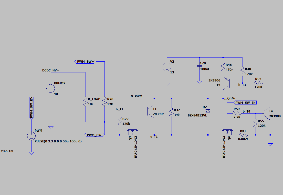
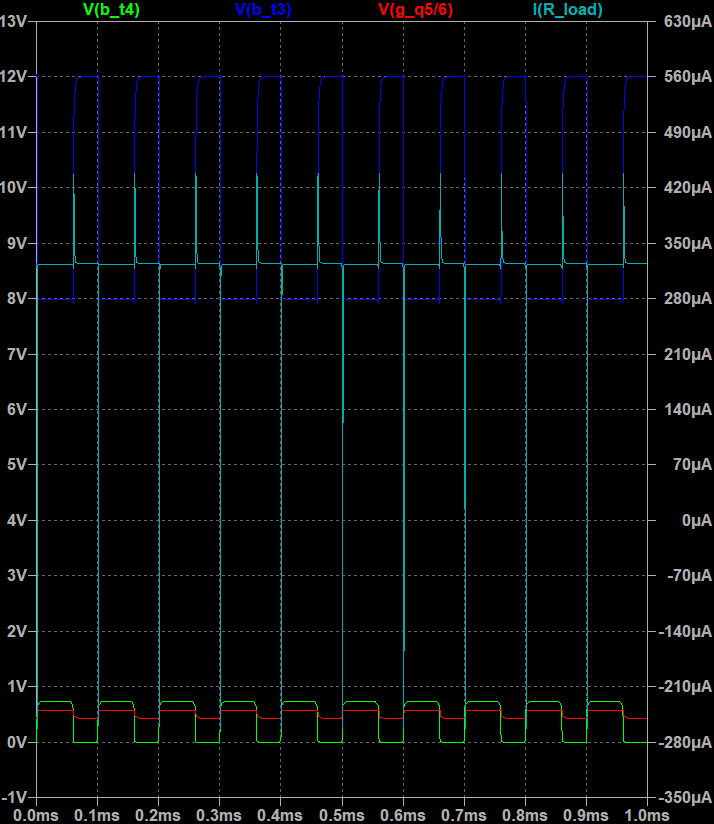
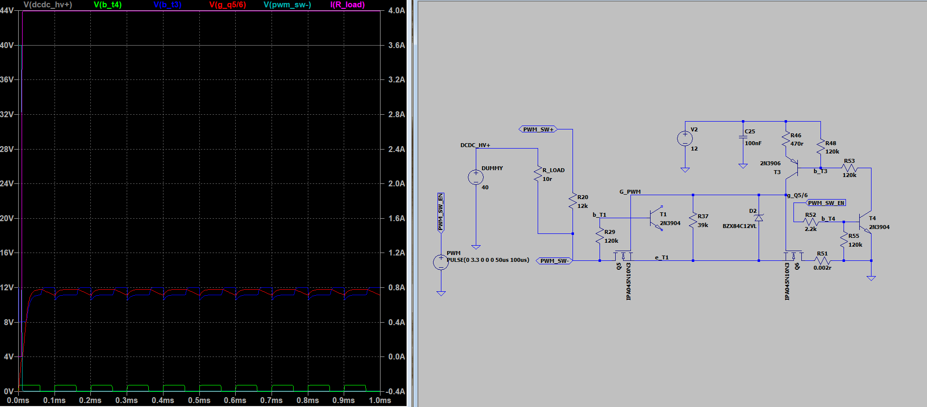
Have you simulated the PWM switch circuit already or do you have any prototype ready?
I don’t like the simulation results in LTspice.
By the way I own a SAS1000 and a IT6513C from ITECH so in case you will have ready made boards we can run some tests before summer
Finally back from Christmas + new year break
I did simulate the PWM circuit before for a solar application and it was copied from the PWM 2420 LUS, which is working fine. So far I didn’t test it in this circuit. I just got a first PCB and hope to finish soldering it today.
Looking at your LT spice schematic I realize that the LED application (I guess R_LOAD should be the LED) might need some small modifications. In contrast to the solar panel, it does not generate a voltage below GND to switch off T1. Can you take out T1 and see if it works?
Frohes Neues Jahr! 
I did that last week, switching works without T1.
Please let me know if you are ready to implement the LED feature in your FW, I can prepare some guidelines for you.
Hi, maybe i am wrong here and this topic is quite old in teh meanwhile bu ti have a question that propably best fits here. Actually more and more eKickboards are in the market. I have one wiht a 36 V/ 10 AH fixed Akku pack E-Scooter mit ABE. It is supplied with a 42 V/ 2 A power supply.
My idea is to use a single solar module that could also be used as roof for a charger station to charge it. The supplier says it has a built in BMS but needs const 42 V and externally limited 2 A/ max. 3 A to charge.The solar panel i would use is a AE_HSF_HM6-72-370W-400W – AE Solar
It has a Vmp of 41,71 V and Voc of 49,69 V.
Is it possible to modify the design for 42 V output voltage and a const current of 2 A/ 3 A?
It is not intended to charge a battery and use it to charge the eKickboard battery from external battery but due to limited capacity (10 AH) compared to peak power of the solar panel it could of course make sense to switch to a buffer battery when the eKickboard battery is charged. If this buffer battery is charged it could alos be used to charge eKickboards during night time.
This concept could also work with eBikes or other low voltage battery systems.
I´m not an electronic pro but very interested in a solution as this could probably help reduce losses in charging low voltage emobility devices.
Woudl be nice to hear from you.
Tom
Hi Tom,
don’t think that would be easily possible with the current hardware, as the solar panel voltage and the battery voltage are almost the same. So you would need a buck-boost converter topology (something like the LT8708 with 4 switches and 1 inductor).
If you use a solar panel with 18V MPP it is possible to operate the MPPT charge controller in boost mode to charge an e-bike or e-scooter battery. I’ve done that already before.
Hope that helps to answer your question.
Martin