hi,
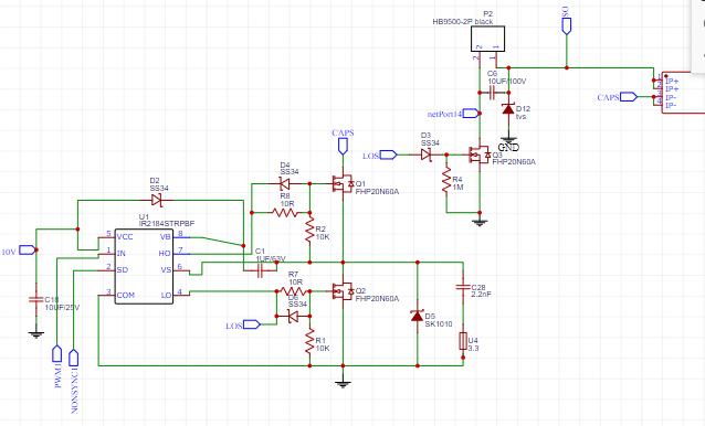
i am trying to build mppt using ir2148
and using arduino nano. unfortunately i am having a problem with my mppt
no matter how much I tried I only got 60-70 efficiency.
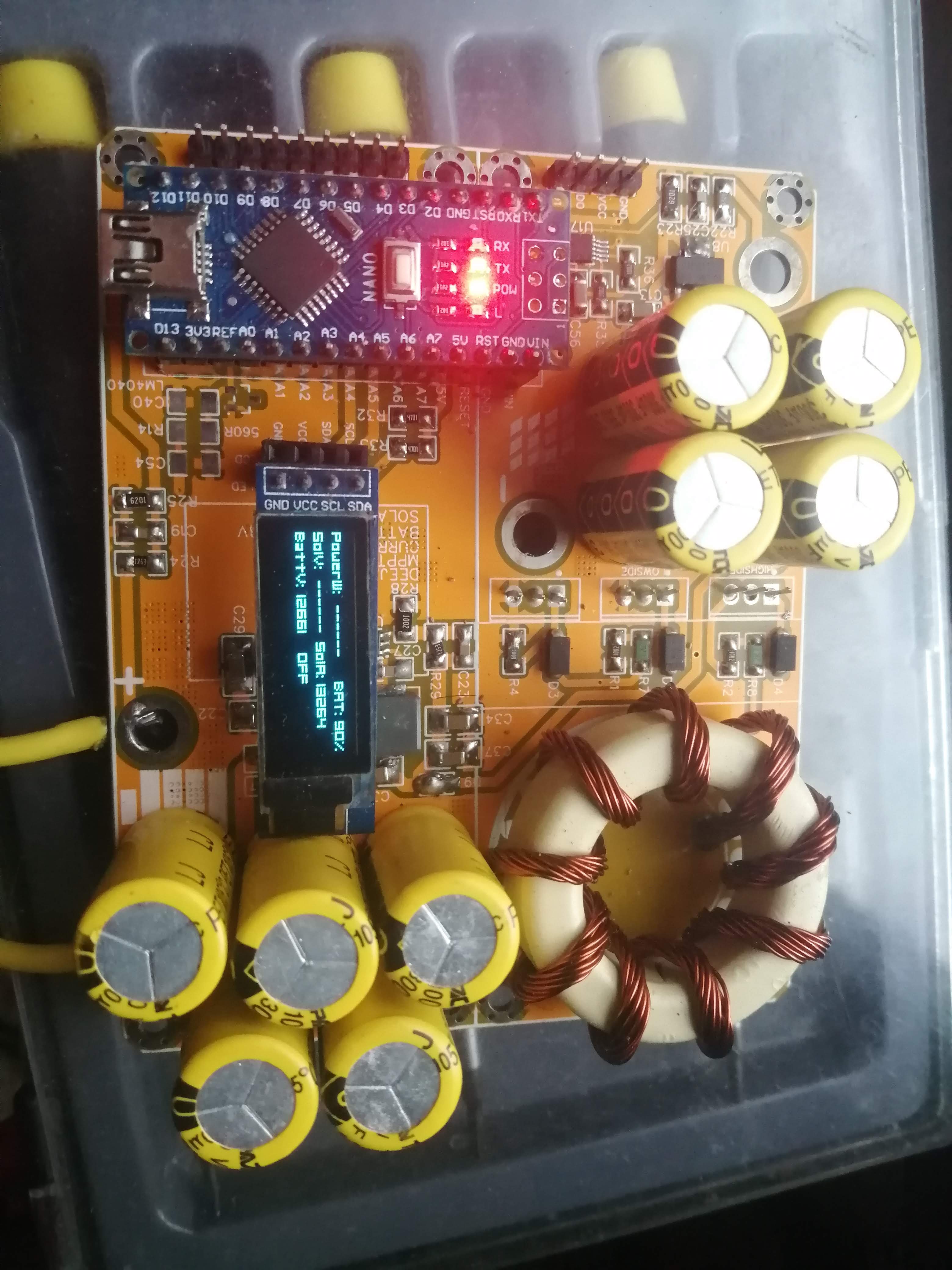
I have 4 pcs 330uf at input. and 5 pcs 330uf at output.
I really need help to find the fault. I also tried to manually increase and decrease the pwm duty cycle to think its code problem. but I only get the same results. its always get about 60-70 percent duty cycle. help is really much appreciated
That’s impossible to tell if you only provide an incomplete schematic and no additional information like firmware, board layout or oscilloscope shots. It can have so many causes…
I can’t find the inductor in the schematic. Looking at the image it seems like it has quite low inductance (only very few windings). Which is the core material of the inductor? Maybe it’s not meant to be used for SMPS applications.
i ma using 80khz for the Switching frequency. the inductor is place directly in pcb. since theres is no package like that in the easyeda. I also manually draw the inductor image. here’s the inductor I use.
did you check the link for the inductor?
that is the inductor I used. I tried also inductance about 55uh but I got the same results.
already tried also manually varying the duty cycle but also got the same results.
What is the solar panel voltage? You use 600V MOSFETS which have an incredible high RDSon of 0.4 Ohm. 60V MOSFETS have usual RDSon < 0.015 Ohm. The high voltage MOSFETS are also slower switching and have high gate charges. Did you checked the temperature of your transistors during operation? I expect they are too hot to touch. Except that, please consider the things Martin said about the inductivity (saturation etc).
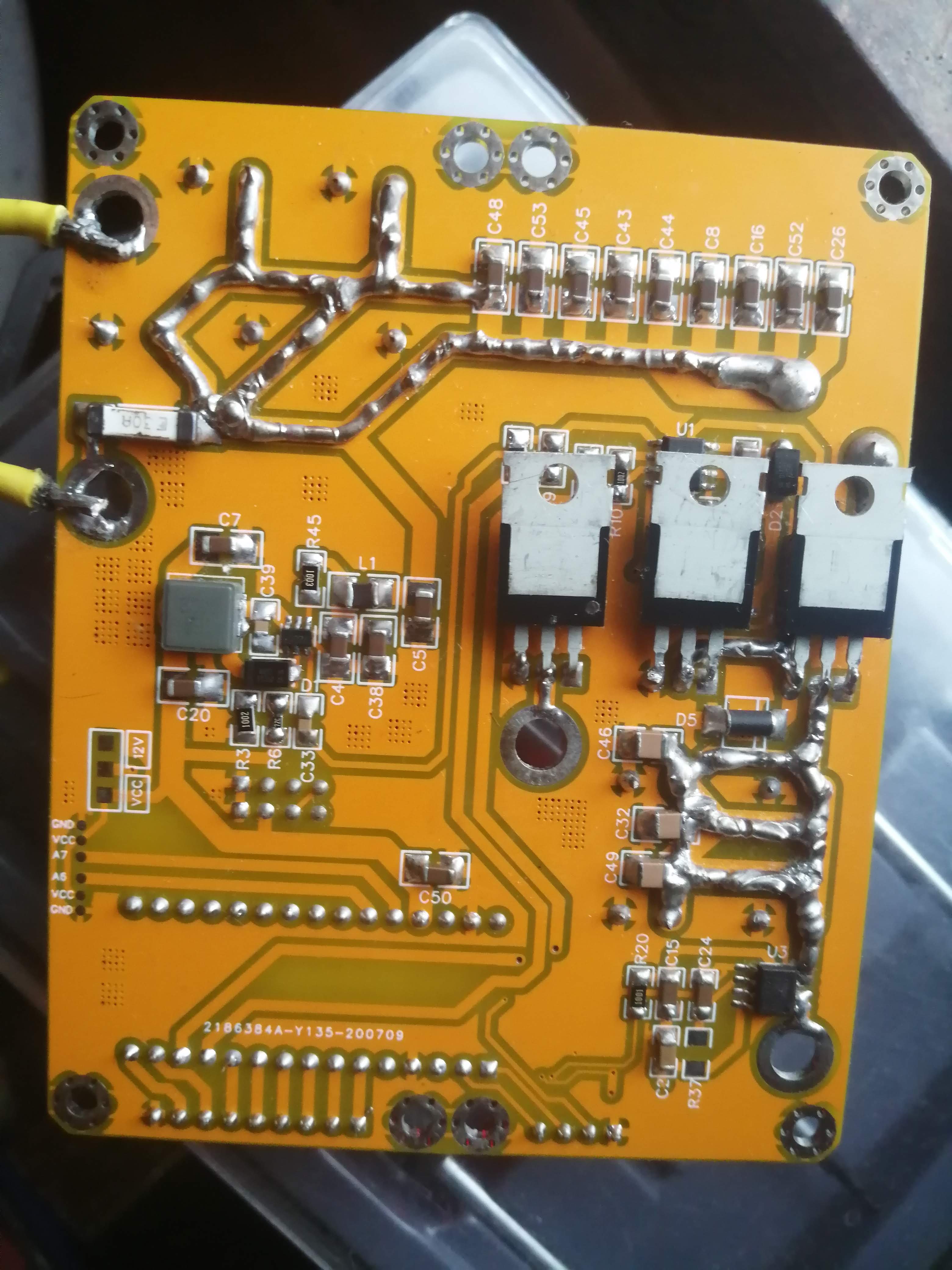
The schematic does not show the exact position of your inductance. If you have 30% losses, the energy have to go somewhere, usually converted to heat.
For further analysis: Please check current through inductance with an oscilloscope, does it show nice triangled shape whithout saturation effects.
Check current through BOTH mosfets (also oscilloscope), maybe the edges of the two PWM signals at the MOSFETS does not have enough dead time. Usually this is forgotten to set the correct dead-time.
one thing i notice the inductor will produce noise
when the mppt is working it charge the battery when the sun goes down. the charger will goto off state. then some weird noise in the inductor. i can hear it if i put my ears near the inductor.