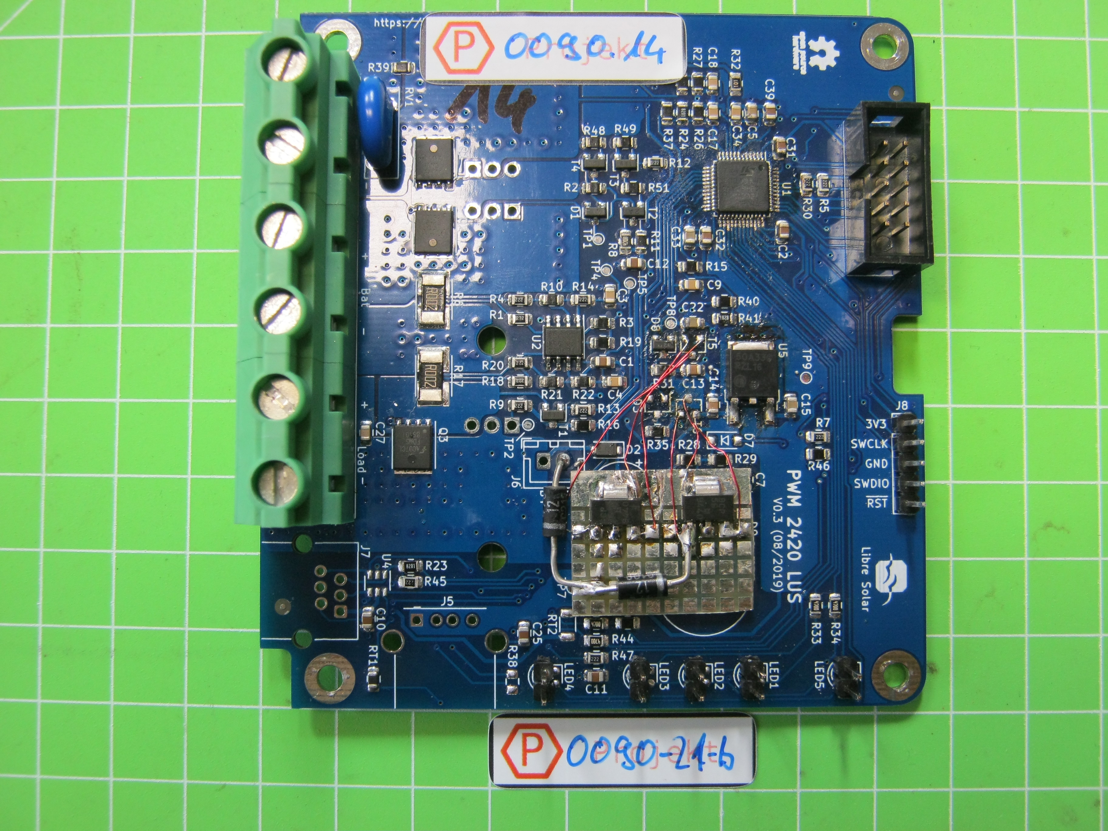
If battery voltage above 24V is used, it should be considered to replace T5 and T6 transistors with higher power rating, for example BCP56, which is SOT-223 case.
Long version:
PWM2420-LUS is used as charger for a battery 20x 1.6V NiFe-accumulator (aka Edison-cell). After one day of usage, PWM2420 charger was defective. I know, this is off-label-use of charger. Charger was used with 1.3’’ OLED display
Damage analysis:
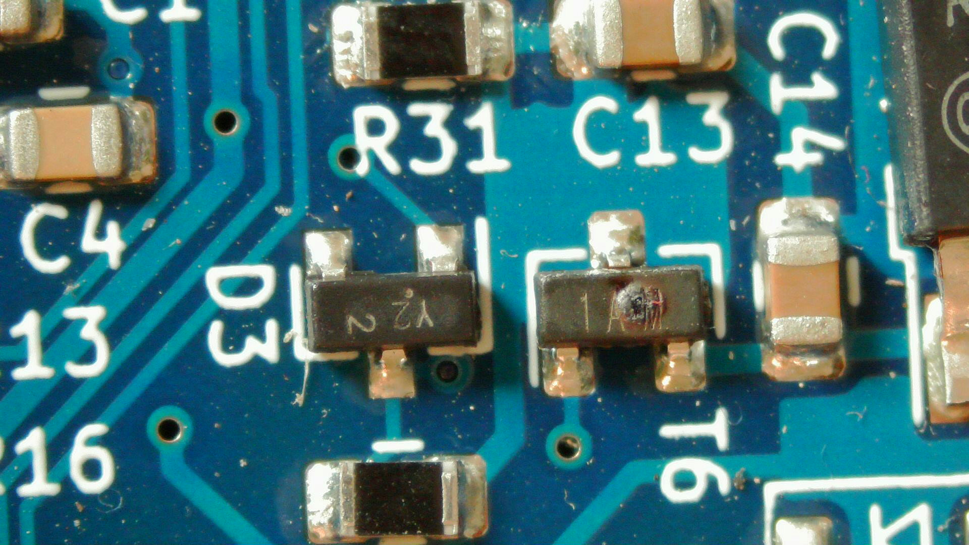
T6 was blown, secondary defects D3, T5,D8,U5 and controller U1
Presumed cause:
Because of the high voltage drop over T6, the transistor overheated and got broken. U5 got too much voltage and was destroyed, U1 got too much voltage and was destroyed also.
Recommended modification:
Change Transistors with higher power rating. This failure could happen with LiIOn-cells also when voltage rises over 24V. SOT23 is maybe little bit too small for power handling.
Further recommendation:
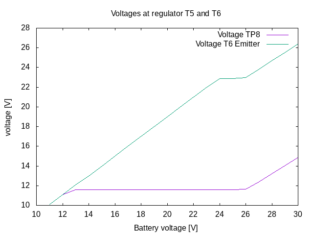
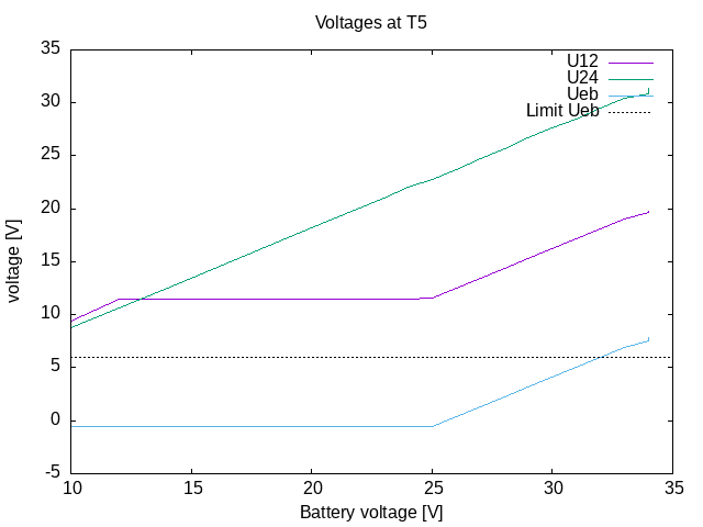
During analysis, there was a weak stabilisation of 12V and 24V voltages over rising of battery voltage. At that time controller was stopped, so no power was drain from 12V rail. It seems current through D3 rise 12V rail to higher level, so 24V level rises also. I recommend to use a 24V (D3) connected to ground directly to get better regulation behaviour.
Wow, thanks a lot for tracking down the issue and posting this great analysis!
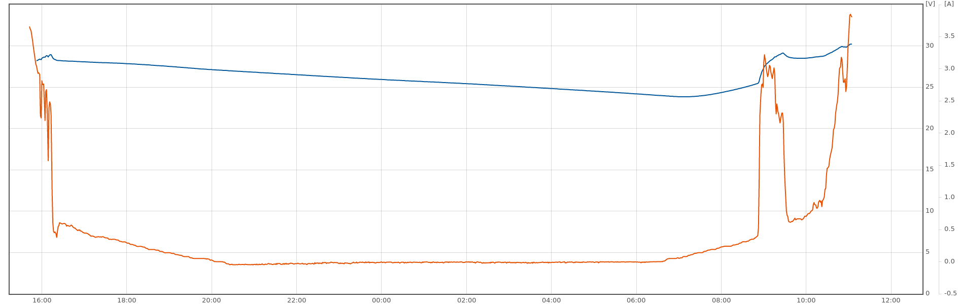
So the only power drawn from the 3.3V rail was the OLED display and the charge controller itself (MCU etc.)? I did check the temperatures of T6 with a thermal camera some time ago, but only went up to around 30V, which is the maximum expected in 24V application. And it was either with no additional consumer in the UEXT port or also with a 0.96’’ OLED (not totally sure anymore), as we are using a separate power supply via connector J6 for our communications module.
I decided for this approach with two 12V Zeners to save one additional type of component. But actually didn’t consider that in case of no MOSFET driver load the current through D3 has nowhere to go and even the tiny current can raise the voltage of the 12V rail. That’s a very good insight. We could put two 12V Zeners in series (but referenced to GND) so that we can reuse parts already existing on the board.
Just thinking that the failure could also be caused by the unstable voltage regulation. If the emitter voltage of T3 raises, also the input voltage for the LDO U5 will increase and could reach more than 30V (exceeding its absolute max. rating). If U5 fails short, the 3.3V rail will raise, eventually causing a short, e.g. in the MCU (U1) and afterwards T6 will burn because it overheats. Does that make sense?
Mhh, looking at your graph, the battery voltage only got slightly above 30V. That should not have killed the LDO…
Independent of the root cause, I agree that we should increase power rating of T6 to have some more margin.
I will also do some further tests with the thermal camera and double check (probably next week).
Out of interest: Which tools are you using to log the data as shown in the graph? I assume you get the data from the charge controller directly, but I see that you didn’t even solder the serial interface connector.
For the zener-diode, i also use 2x12V in series, for reduce amount of different parts its ok. 24V zener is also not so common (27V is common). Extra load was only OLED-Display and a serial converter (see next message) only.
The damage mechanism is not completely understood by me yet, which part failed first. I expected to be T6. For the regulator i expect thermal shutdown feature protects the device from overheating. Maybe MCU was damaged by other event. At least the fuses to battery were tripped during the event maybe because of untwanted switching on of MOSFETs? I run the device already with my modification, we will find out if any other damage will occur.
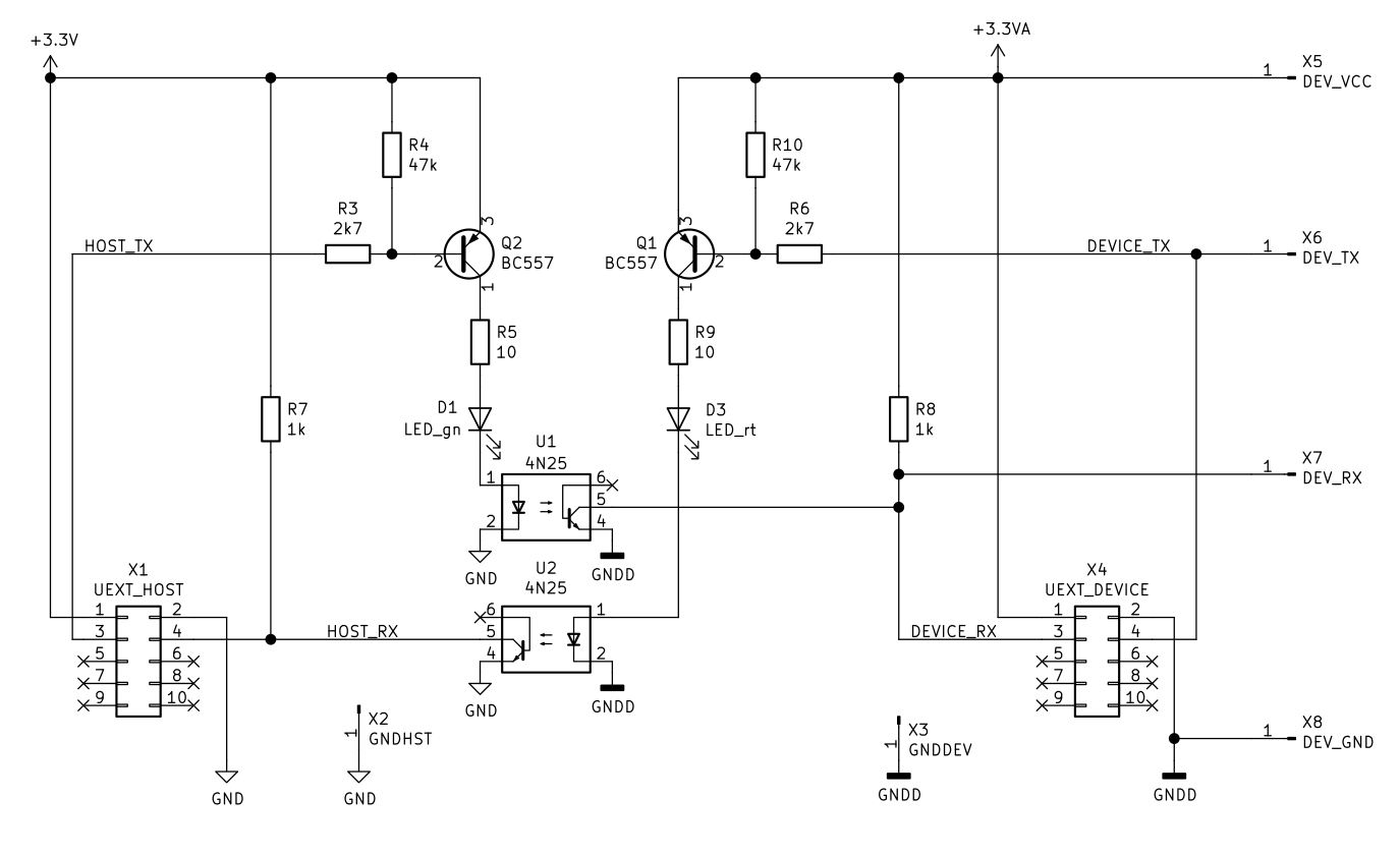
For data logging i use https://volkszaehler.org/ vzlogger feature, [frankrichter] recommended me to use that. Data is written over UEXT-UART in obis-format, modification in sourcecode was made. An opto-insulated converter prevents ground loop because we cannot use a common ground for all batteries.
The converter is made of opto-couplers because i have a bunch of it, so converter is super cheap, and it does consume less power than a Analog Devices uart insulator. Optos are fast enough for 9600/19200 Baud.
Ah, nice. Those 4N25 optos are very cheap, indeed. In the data manager based on ESP32 I used the SI8621AB for the serial interface. It has both directions in one device and supports higher baud rates, but two of the 4N25 are still cheaper…
Never heard of the obis-format, looks interesting. Frank also showed me the Volkszaehler, but didn’t try it out yet. I was using open energy monitor so far, which has a quite simple JSON API.
If the modification with the more powerful transistor is implemented, maybe a solar-bootstrap (similar to MPPT-charger) can be implemented too? If the battery pack is discharge-disconnected by BMS, the PWM2420-charger will not charge without voltage at battery connector.
Didn’t fully check, but I guess this would be difficult with the common positive design of the PWM charge controller. Solar+ vs. GND is always also the battery potential, so the GND of the supply would have to be decoupled from the “other” GND somehow…
Finally found some time to further investigate the issue.
I can confirm that the MOSFET supply voltage starts to rise at around 26V fed into the battery terminal. For further testing, I set the battery voltage to 32V, resulting in a MOSFET driver voltage slightly above 16V.
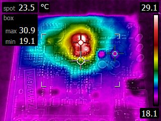
Here is the thermal camera image after 10 minutes without any load plugged into the UEXT port:
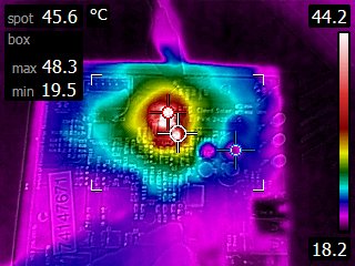
The next image shows the temperatures after I applied 20 mA to the 3.3V rail for around 10 minutes using an adjustable load:
So we can clearly see that the temperature of the LDO rises from 30°C to 50°C for the 20 mA increase of current. However, the hottest point is still the LDO and not the small transistor T6.
According to this website the current consumption of the OLED is much less than 20 mA and also your optocouplers should not consume a lot, so I’m not sure if excessive heat was the reason of the failure.
I am not sure what was the initial failure cause. The blown T6 could be a followup after some other incident. Because Microcontroller was damaged and LDO was damaged i am sure the 3,3V rail was part of the incident and an overvoltage occured there.
For now, i run the modified PWM2420 (with the more powerful transistors) at the NiFe-Accumulators with Ubatt>32V peak voltage. No incident happened so far.
I run 4 more unmodified PWM2420 at Ubatt peak 31.6V, 28.8V (two units), 15.6V. This units did not show any issue, but not all of them have OLED display as load. I will equip all of them with OLED load also.
I did several checks, i cannot reproduce the damage at the moment.
OLED-current is around 8mA at typical display content.
I run a new build PWM2420-LUS for one week at UBAT=32V, without solar power, now. No damage occured. OLED and optical serial adapter are connected. UBAT-current seems to be around 15-20mA, fluctuating.
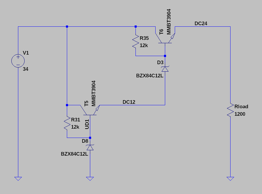
I simulated Transistor behaviour with Zener-Diodes. At T5, maximum U_eb voltage is exceed, i tested it several days with U=34V, no damage occured.
I tested voltage regulator LP2950 (3,3V LDO, ON-Semi brand) with Uin=40V and Load=20mA for 3 days. Although the 40V exceed maximum allowed voltage, no damage occured.
Interesting that the LP2950 easily survives 40V. If they specified that in their datasheet, we could get rid of the second emitter follower completely
One question regarding your LT spice simulation: Are you saying that Vbe of T5 (maximum rating: 6V) is exceeded in the circuit shown in the picture? Didn’t rebuild the circuit to verify, but don’t understand why it could be exceeded. Or maybe I misunderstood?
I also was surprised the LP2950 survived. But i tested one sample only. I am sure there are also weaker parts which will blow up at 40V.
The test for exceeding Ueb for T5 was made because of the voltage rise on the 12V rail caused by current through D3. The current cannot run anywhere so it lifts the emitter voltage on T5.
So i strongly recommend the previous idea, to connect D3 anode to GND level.
I want to give an update. The incident seems that it was a single unknown event. During the year i build 5 more units of PWM2420-LUS, unmodified with original transistor. They run with max. battery voltages between 28 and 32.8V. No more blowup occured.
Thanks for posting the update, @xsider. Happy to hear that it’s working fine.
BTW: Did you experience any issues with the voltage control of the PWM charge controller? We had some issues in seldom cases where the PWM control algorithm didn’t react fast enough so that the battery voltage got too high for a few seconds. It should have been fixed with this commit (which is currently still in the develop branch only).
I did not observed for overvoltage incidents. The vzlogger records data from BMS only at the moment. If PWM control gives an overvoltage to the output the BMS isolates the battery and i do not see the overvoltage spike in my recorded data. The data is also averaged over 30 seconds.