yes, the FET is indeed for reverse polarity protection and reverse current flow. It’s connected to LS_DRV to save the parts for an additional MOSFET driver, so it’s always enabled as soon as the DC/DC is enabled, which only happens if a plausible solar voltage is measured. The diode prevents discharging of the (internal) gate capacitance during the off-time of the low-side MOSFET.
Does the extra Rds(on) resistance between the panel and gnd cause any bother or skew panel voltage readings any bit? Do you need to periodically switch on the buck converter in order to be able to read panel voltage?
I have made some charge controllers using LTC4357 to get around this. I’ve also seen designs with the reverse blocking fet on the highside but I think those were noisy. Am working on a new design now that will use the PIC programmable gain amplifier peripheral and hopefully the same protection FET as used in this design. If it works it will let me eliminate 2 hard to get / out of stock ICs
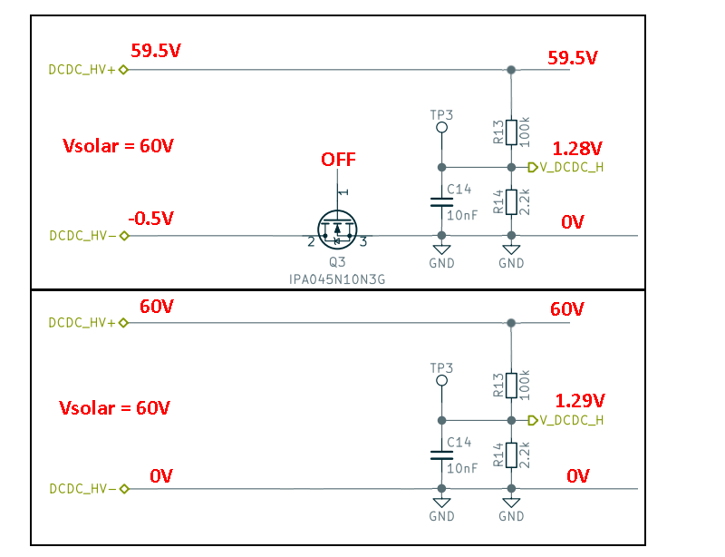
I was also confused at first. As far as i understand, there is no need to turn on the mosfet periodically, because the body diode of the mosfet connects GND and Solar- (see Diagram 12: Forward characteristics of reverse diode in Mosfet datasheet: about 0.5V VSD, even at the marginal current going through the voltage divider), but still there is an error of this voltage drop introduced.
I don’t think the small error is a huge problem for solar panels, as the MOSFET will be on as soon as you do the MPP tracking.
Putting it to the high-side should also be possible, but in that case the source with the pull-down resistor would point towards the solar panel and (if I remember correctly) I was a bit concerned if the reverse polarity protection would still work reliably in that configuration.