Some details:
Firmware: main branch complied as board mppt_2420_hc@0.2.0
Battery: lead acid battery @12v
High voltage input: a dc power supply @25v limited current under 1A
Load: no load connected
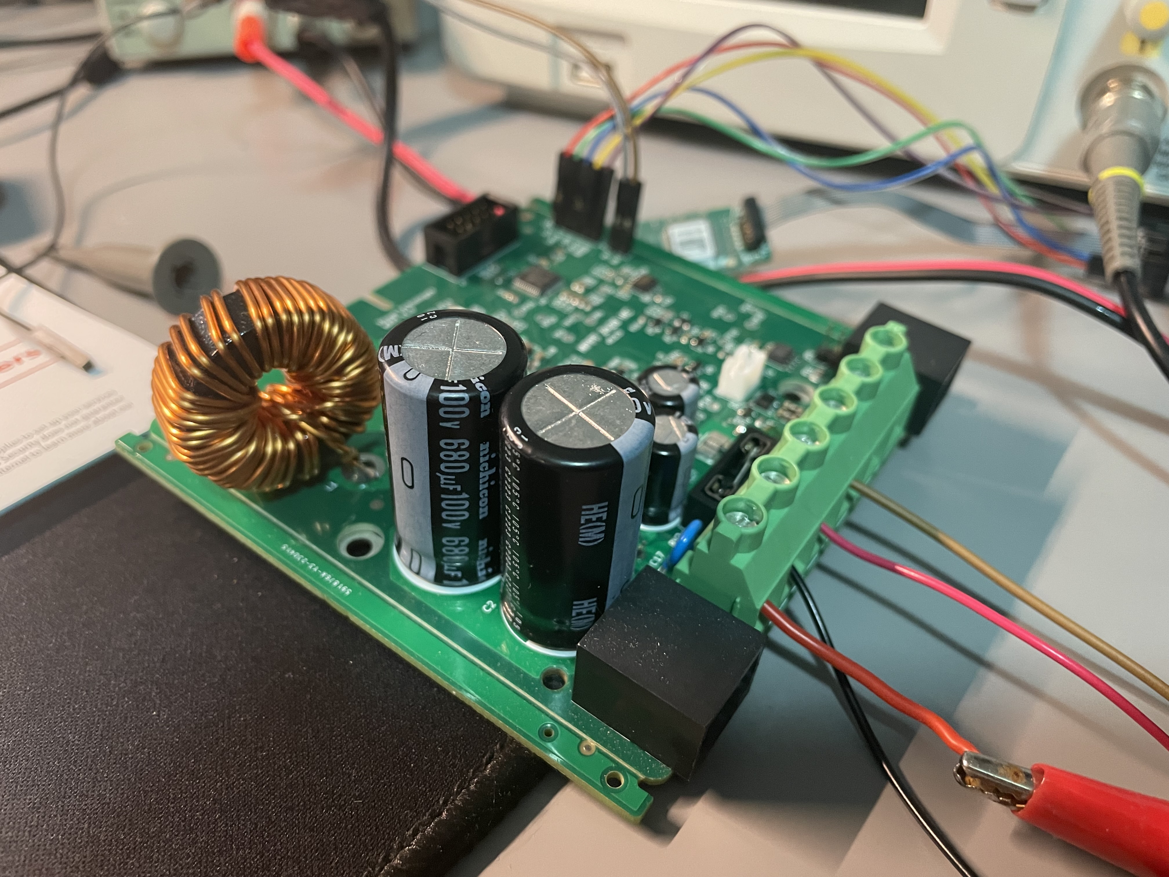
Inductor: a cheap 100uH 30A inductor bought on aliexpress(Could be the problem? Though my charging current is only several hundred mA to 1A)
FETs: Q1 Q2 Q3 Q7 are IRF540N
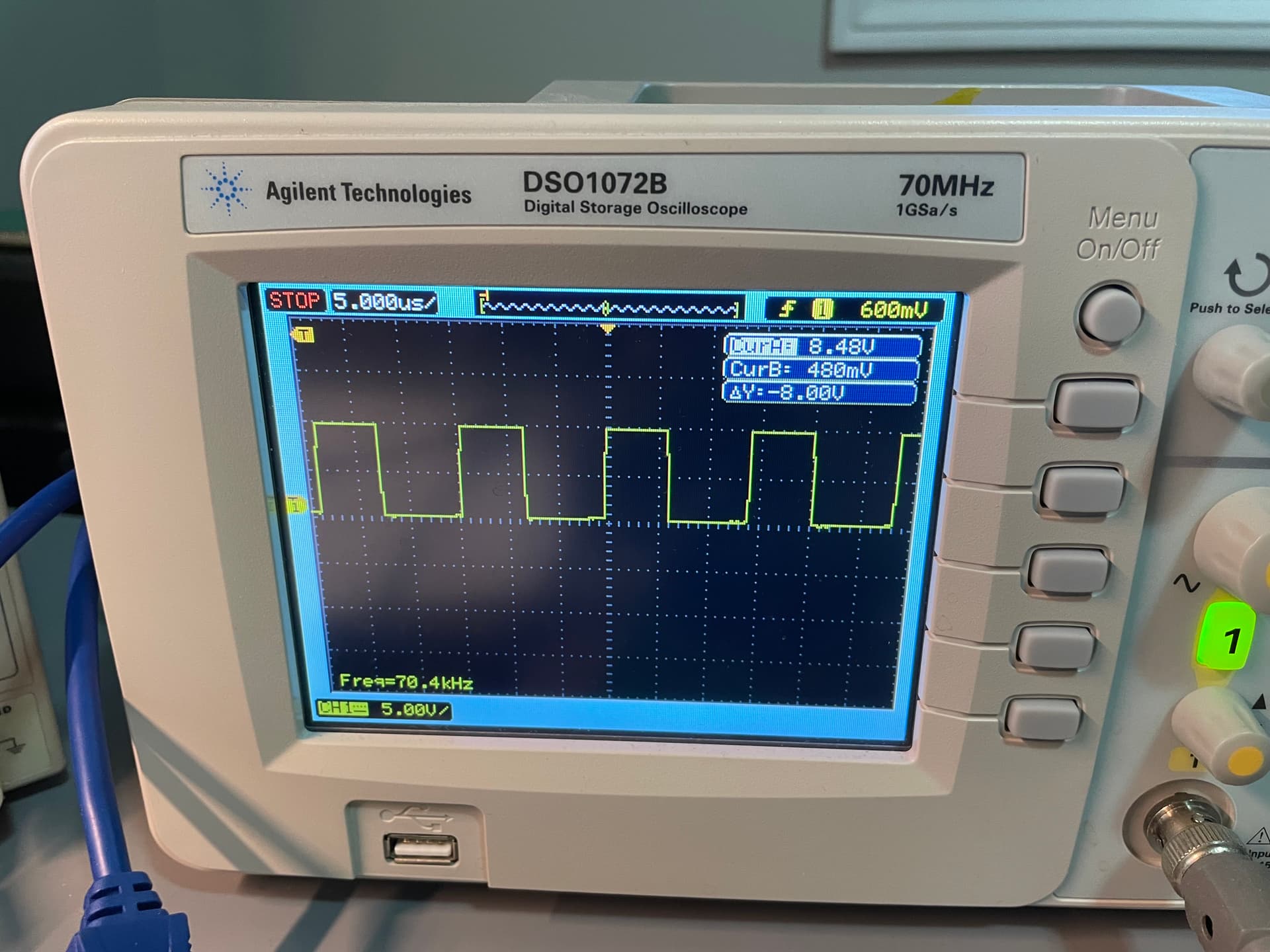
I hooked up a scope and measured switch frequency of the charge pump is about 50% duty @ 5k Hz and the voltage on TP4 is around 11v, the voltage on TP10 is around 17v.
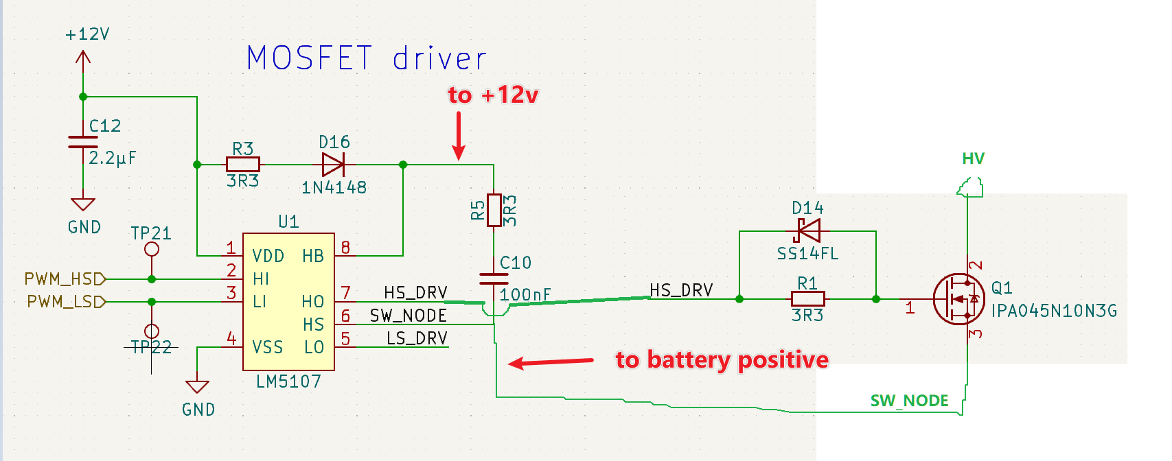
I looked the schematic the 12V from T10 only supplies charge pump and gate driver. Charge pump is for controlling the high side load switch. The load switch shouldn’t take too much current.
It is the gate drive? Although I looked the datasheet says LM5107 only takes several mA.
What could be the problem?
Thank you and really appreciate any input.
I haven’t had such an issue before and I have operated the charge controller at 80V solar input and 24V battery output.
I had an issue with the supply rail selection circuit before, but didn’t really understand the root cause back then. Maybe you could take out T2 and Q4 so that always the low voltage side is used and less voltage has to be dropped in the transistor. What is the voltage on TP9?
Other than that my only explanation would be that there must be a leakage current in the charge pump or the LM5107. Maybe a bad solder joint somewhere? Under normal conditions they should only draw current in the mA range.
1 Like
Thank you very much for your reply:)
I will try take out T2 and Q4.
I measured TP9 before, if I do not remember wrong the voltage was around 12V no matter I enabled the high voltage rail or not(in may case 24v dc power supply).
I will thoroughly exam the charge pump and lm5107 soldering again and report back.
I took out T2 and Q4.
No matter power supply is applied or not the TP9 is around 10.8V
Battery is 11.4v. Power supply is set to 24V.
No overheating for T10 for now. But I notice the mppt seems not charging. The current reading on my supply is zero.
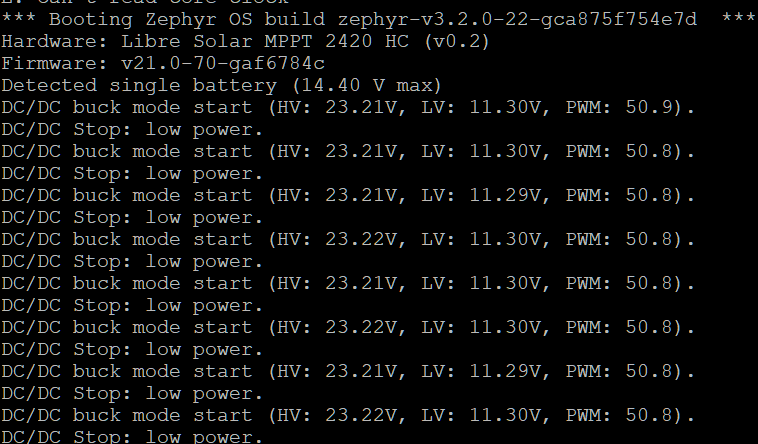
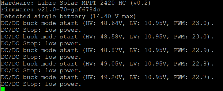
And I also connect to the uart. It shows “DC/DC stop: low power” once a while.
When it shows DC/DC buck mode start I could measure gate drive sending PWM signal to FETs on R2. The frequency is around 70kHz and magnitude is same on 12v rail which is about 10.8v in my case. The duty is around 50% which is correct as shown in UART message.
Do I need to config battery chemistry and cell numbers in firmware to make it work? How can I enable more debug information in firmware.
Thank you again for your help.
Update: I used a multi-meter to measure across c10 the voltage is only 1.1v when “DC/DC buck mode” start message shows on UART. Is it possible that I changed the FETs to IRF540N, I might also need to change the bootstrap components to make the gate drive properly work?
Ok, that’s certainly not correct and it won’t work with a gate voltage of 1.1V. I don’t believe it’s because of the different FETs. They will mainly affect the current capabilities. The gate charge doesn’t look extraordinarily high.
I would suggest to check all voltages around the LM5107 and see if they are plausible. You may also want to check C10 with an oscilloscope.
The DC/DC stops at too low power if it can’t get sufficient current for about 10 seconds from the input. Maybe it’s an issue with your power supply. Lab power supplys don’t have the smooth IV curve as actual solar panels have, so the charge controller may have difficulties finding the MPP. You could try to increase the power limit at your input power supply. Or try with an actual solar panel.
1 Like
That’s also what I think about. That gate voltage should be > 10 cause the gate drive is supplied with +12v. I will dig around the LM5107 and see if I could find more.
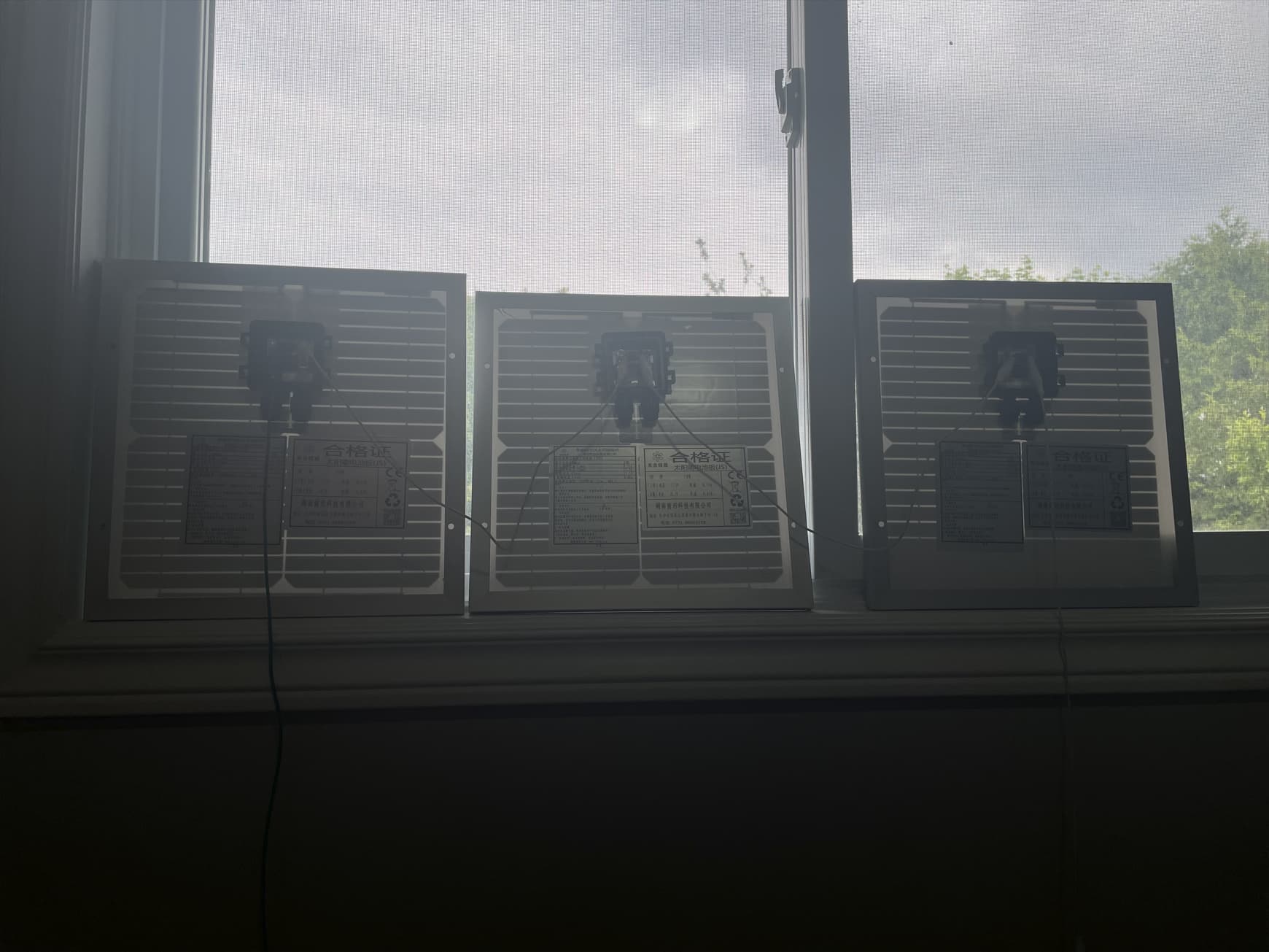
I also tried three 10w 21.5v solar panel in serial(sunlight is not ideal in my place right now, it has been cloudy/raining for several days). The UART still reports “low power”. Although this might be the gate charge is not enabled so the program can not detect current flow through battery.
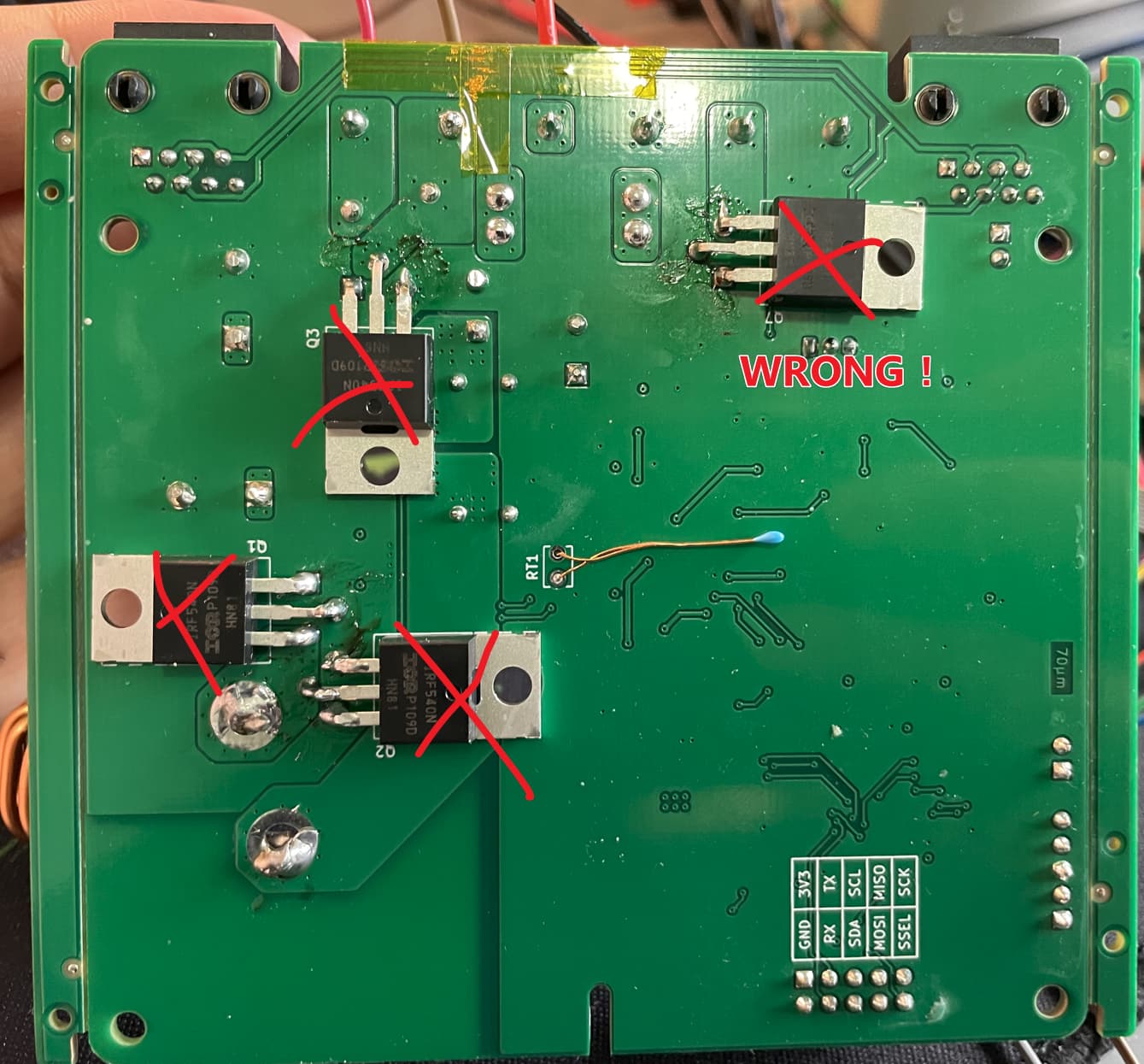
I am an idiot. I spent last week chasing the ghost and finally found the problem.
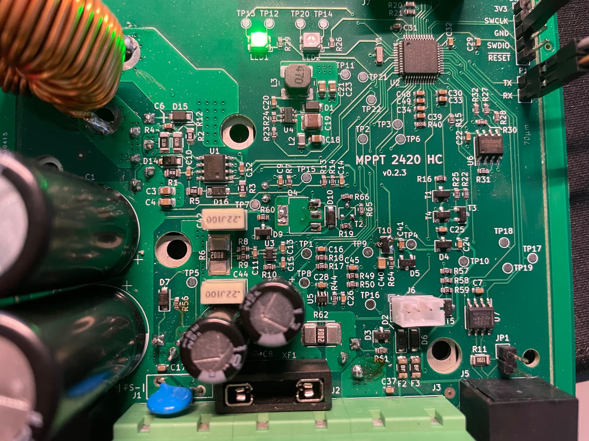
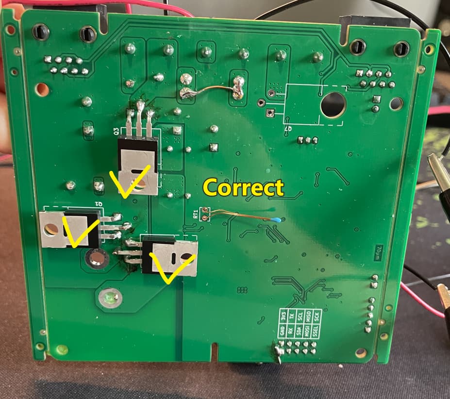
I mount all the power mosfet in wrong direction.
I didn’t know why this looks so correct when I soldering the mosfet on. I didn’t even check the schematic.
Anyone who gonna make 2420HC later do not make same mistake as me…
Picture below shows the correct way to mount the FETs
1 Like
Great to hear that you found the solution!
Is it all working fine now?
1 Like
Haven’t test all scenarios and functions. But now its working. Thanks man.